2 layers57.3 × 19 mm

 jacko465/stm32_blackpill_pid_controller
A PID-based motor control system for the STM32F411 Black Pill microcontroller, designed to control 4 DC motors with encoders via H-bridge drivers (e.g., TI DRV8874).
Driver board is an open-source printed circuit board by jacko465, from the jacko465/stm32_blackpill_pid_controller repository on GitHub. It is a 2-layer board of 67.5 × 71 mm with 26 parts on 66 nets, routed with 303 tracks and 50 vias.
Its parts include 6 resistors, 1 IC and 1 connector.
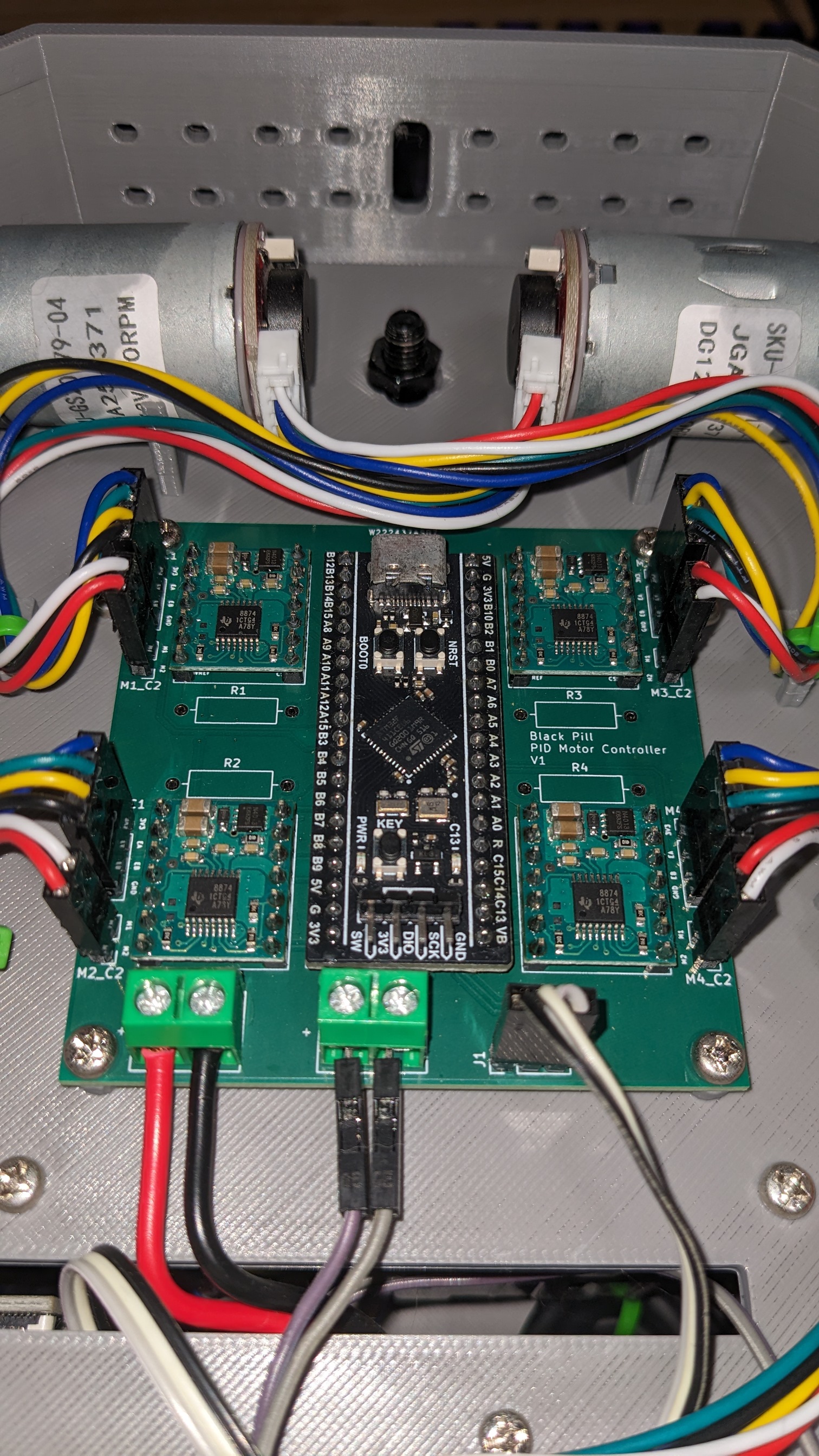
v1 deployment of the PID controller. With Pololu 4035 driver modules
A PID-based motor control system for the STM32F411 Black Pill microcontroller, designed to control 4 DC motors with encoders via H-bridge drivers (e.g., TI DRV8874).
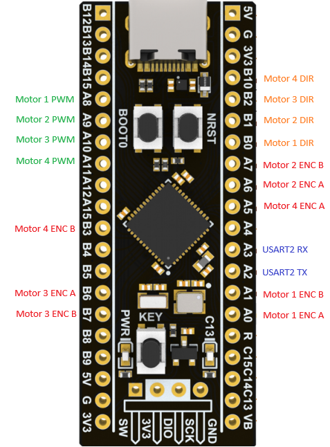
| Function | Pin | Timer/Channel |
|---|---|---|
| Motor 1 PWM | PA8 | TIM1 CH1 |
| Motor 2 PWM | PA9 | TIM1 CH2 |
| Motor 3 PWM | PA10 | TIM1 CH3 |
| Motor 4 PWM | PA11 | TIM1 CH4 |
| Motor 1 DIR | PB0 | GPIO |
| Motor 2 DIR | PB1 | GPIO |
| Motor 3 DIR | PB2 | GPIO |
| Motor 4 DIR | PB10 | GPIO |
| Motor 1 Encoder A | PA0 | TIM5 CH1 |
| Motor 1 Encoder B | PA1 | TIM5 CH2 |
| Motor 2 Encoder A | PA6 | TIM3 CH1 |
| Motor 2 Encoder B | PA7 | TIM3 CH2 |
| Motor 3 Encoder A | PB6 | TIM4 CH1 |
| Motor 3 Encoder B | PB7 | TIM4 CH2 |
| Motor 4 Encoder A | PA5 | TIM2 CH1 |
| Motor 4 Encoder B | PB3 | TIM2 CH2 |
| USART2 TX | PA2 | USART2 |
| USART2 RX | PA3 | USART2 |
| LED | PC13 | GPIO (onboard) |
Default PID gains (defined in motor.h):
This project has been coded for EN/PH driver control mode
The motor.c module provides:
Motor_SetTargetRPM(): Set target velocity in RPMMotor_Forward(): Drive motor forward with duty cycleMotor_Reverse(): Drive motor in reverse with duty cycleMotor_Break(): Active braking (both H-bridge outputs high)Motor_Coast(): Free-running coast (both outputs low)This project uses PlatformIO. To build and upload
The Error_Handler() function provides visual feedback via fast blinking of the onboard LED (PC13) if system initialization fails.
| Qty | Value | Footprint | References |
|---|---|---|---|
| 6 | R_Small_US | Resistor_THT:R_Axial_DIN0309_L9.0mm_D3.2mm_P12.70mm_Horizontal | R1, R2, R3, R4, R5, R6 |
| 2 | Screw_Terminal_01x02 | TerminalBlock:TerminalBlock_MaiXu_MX126-5.0-02P_1x02_P5.00mm | 5V_IN1, VBAT1 |
| 1 | Conn_01x03_Pin | Connector_PinHeader_2.54mm:PinHeader_1x03_P2.54mm_Vertical | J1 |
| 1 | M1_C1 | Connector_PinHeader_2.54mm:PinHeader_1x04_P2.54mm_Vertical | M1_C1 |
| 1 | M1_C2 | Connector_PinHeader_2.54mm:PinHeader_1x02_P2.54mm_Vertical | M1_C2 |
| 1 | M2_C1 | Connector_PinHeader_2.54mm:PinHeader_1x04_P2.54mm_Vertical | M2_C1 |
| 1 | M2_C2 | Connector_PinHeader_2.54mm:PinHeader_1x02_P2.54mm_Vertical | M2_C2 |
| 1 | M3_C1 | Connector_PinHeader_2.54mm:PinHeader_1x04_P2.54mm_Vertical | M3_C1 |
| 1 | M3_C2 | Connector_PinHeader_2.54mm:PinHeader_1x02_P2.54mm_Vertical | M3_C2 |
| 1 | M4_C1 | Connector_PinHeader_2.54mm:PinHeader_1x04_P2.54mm_Vertical | M4_C1 |
| 1 | M4_C2 | Connector_PinHeader_2.54mm:PinHeader_1x02_P2.54mm_Vertical | M4_C2 |
| 1 | MOTOR1 | Custom_Footprint_Library:Pololu_4035_DRV8874_Motor_Driver | MOTOR1 |
| 1 | MOTOR2 | Custom_Footprint_Library:Pololu_4035_DRV8874_Motor_Driver | MOTOR2 |
| 1 | MOTOR3 | Custom_Footprint_Library:Pololu_4035_DRV8874_Motor_Driver | MOTOR3 |
| 1 | MOTOR4 | Custom_Footprint_Library:Pololu_4035_DRV8874_Motor_Driver | MOTOR4 |
| 1 | ~ | Custom_Footprint_Library:STM32 Black Pill | U5 |
The 22 most common of 26 parts.

hackclub/OnBoard
💡 Join 1,000 teenagers and make your first PCB with a $100 grant!


harbaum/galagino
A Galaga, Pac-Man and Donkey Kong arcade emulator for the ESP32

Luos-io/luos_engine
Open-source and real-time orchestrator for cyber-physical-systems, to easily design, test and deploy embedded applications and digital twins.

google/walt
A device for measuring latency of physical sensors and outputs on phones and computers

It measures 67.5 × 71 mm and has 2 copper layers, 1.6 mm thick.
26 parts. The full list of its parts is on this page, with links to each part's symbol and footprint where PCBKit's library has them.
From the jacko465/stm32_blackpill_pid_controller repository on GitHub, at the commit this page was made from: the board is Kicad_PCB/driver_board.kicad_pcb and its schematic Kicad_PCB/driver_board.kicad_sch. PCBKit opens the board in the browser, with nothing to install.
Its repository states no licence, so its author keeps all rights: ask jacko465 before reusing the design.