4 layers175 × 40 mm

 j9brown/bed-lift2
Motorized bed lift system
Bed lift is an open-source printed circuit board by j9brown, from the j9brown/bed-lift repository on GitHub, published under the MIT licence. It is a 4-layer board of 195 × 45 mm with 154 parts on 134 nets, routed with 1,149 tracks and 988 vias.
It is built around the STM32C051C8T6, ISO1640BD and LP2985-33DBVR, with the LP2985-50DBVR, PESD5V0L2UU and S4B-XH-A among its other parts. Its parts include 69 capacitors, 37 resistors, 15 connectors, 10 ICs and 7 diodes. It belongs with the robots and motor control boards and the STM32 boards of this library.


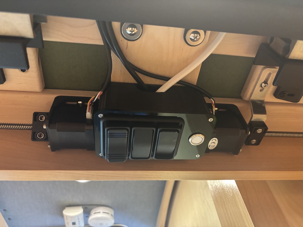
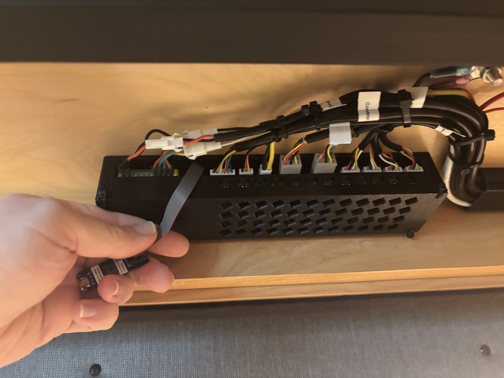
Controls a motorized bed-lift with two synchronized linear actuators for vertical lifting and lowering and two pairs of synchronized stepper motors for horizontal extension and retraction. It fits in the back of a campervan.
Refer to the following documents for design synopsis, schematics, and circuit board illustrations.
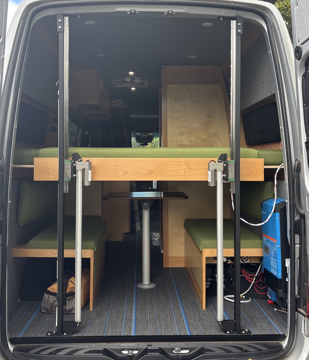
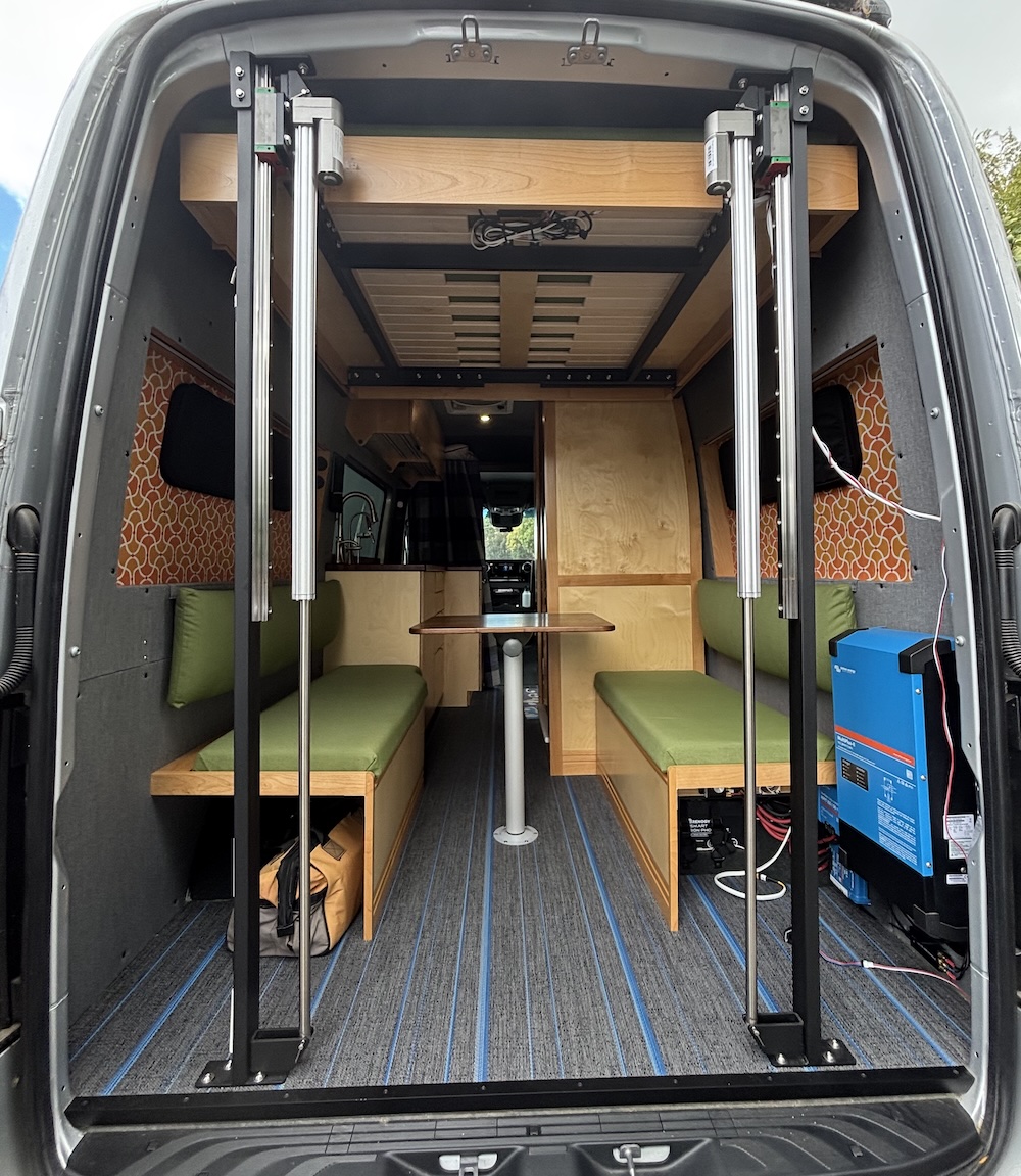
This custom motorized bed fits in the back of a small campervan to allow dual-use of the living area in a standard wheelbase vehicle. In its raised position, the bed platform is only supported from the back which gives it the appearance of a pallet on a forklift, hence the name.
To maximize space efficiency, the bed is designed for sleeping crosswise with the head and feet towards the sides of the vehicle. This choice of sleeping orientation poses unique engineering challenges; it is more common to design lifting beds for sleeping lengthwise with the head and feet towards the front and back of the vehicle.
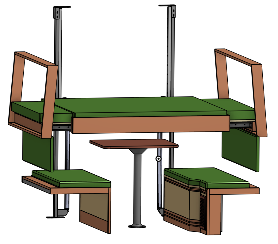
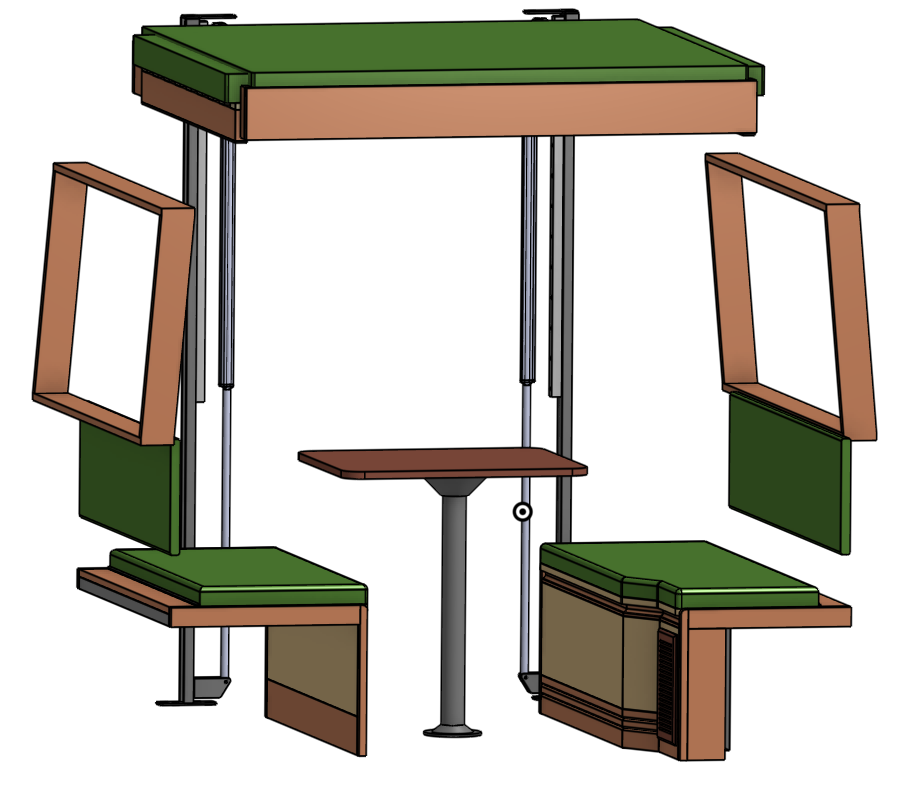
Because the van is narrower at roof elevantion than at sleeping elevation, the bed extends and retracts to span the gap between the main body of the bed platform and the sides of the vehicle. The parts that extend and retract are called the bed wings (aka. wing spans). The bed mattress is made of three cushions: one large central cushion on the main body of the bed platform and two narrower cushions that rest on the two bed wings. The narrower cushions are removed and stowed on top of the bed before retracting the bed wings.
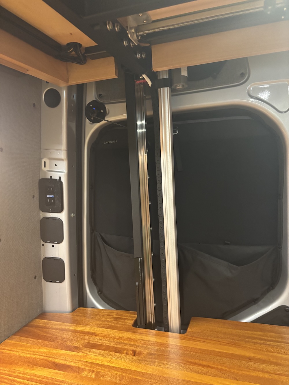
When the bed is raised, the bed wings retract into the bed platform and the platform is cantilevered from steel columns attached to the rear doorframe and floor of the vehicle.
When the bed is lowered, the bed wings extend from the bed platform and rest upon reinforced windowsills to transfer the load of the occupants to the vehicle walls.
The bed has limited load bearing capacity while raised so it must be lowered when occupied or while driving to prevent excess torque through the cantilever. As an advantage, there are no cables, straps, bulkheads, guides, posts, or other obstructions in the front of the living area to support the bed. As a disadvantage, the bed structure is heavy and difficult to build.
Feel free to contact me for advice if you are interested in building a bed like mine (and be prepared for a challenge)!
Video tour of the v0.2 prototype
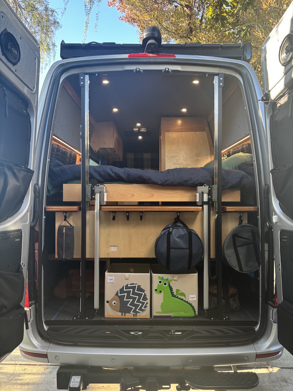
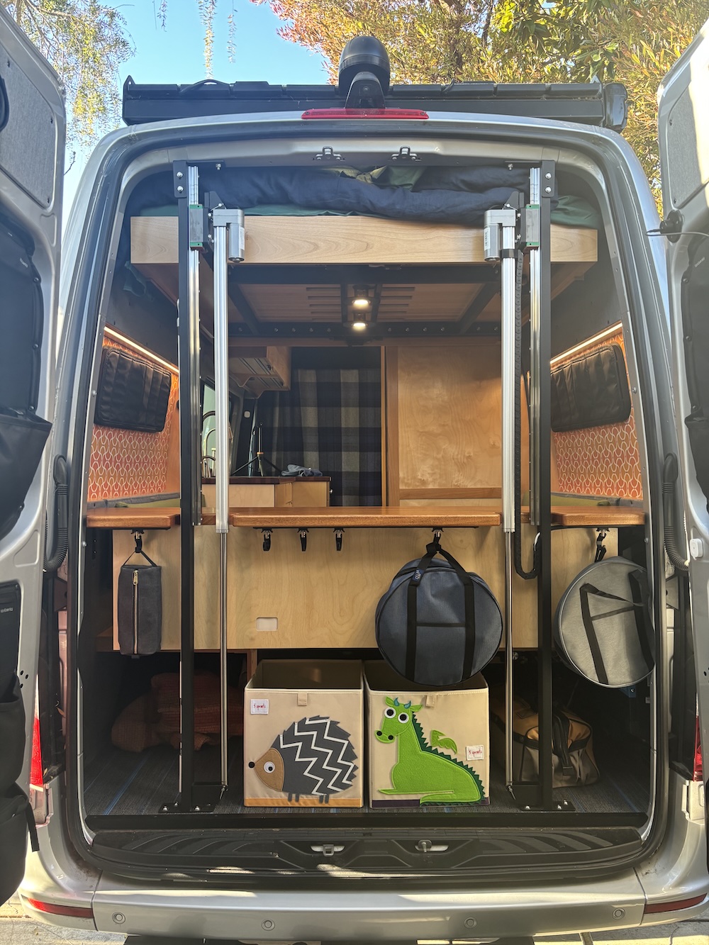
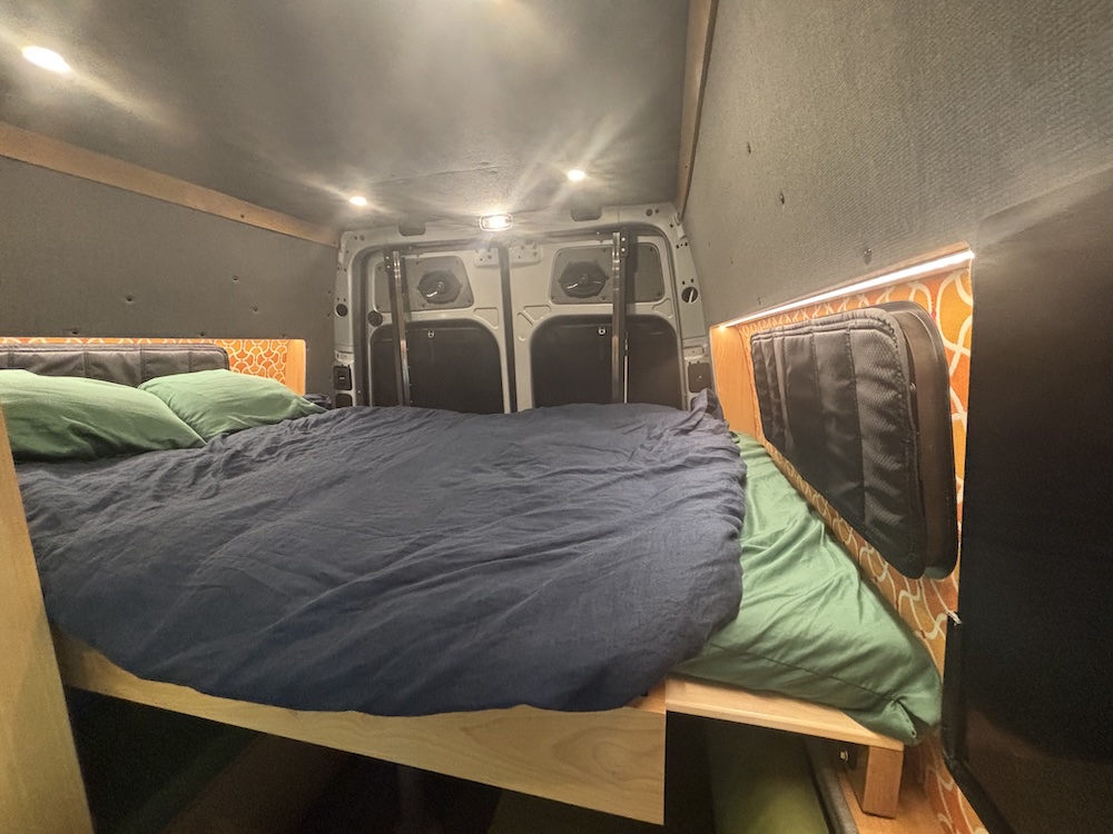
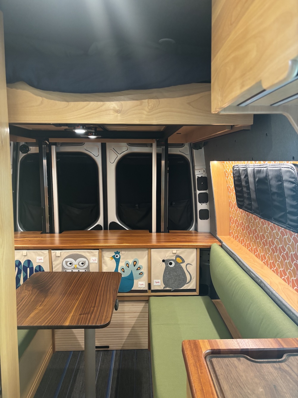
The firmware is based on Zephyr RTOS v4.3 and compiled with west.
Install the Zephyr RTOS SDK tools. You can either follow the Zephyr Getting Started Guide or install an extension for your IDE, such as Zephyr IDE or Workbench for Zephyr, that can install the tools for you.
Install the xPack OpenOCD package for your OS and add it to your system PATH. This step is needed because the version of OpenOCD that is distributed with Zephyr is too old and doesn't support the STM32C0x series of chips. We need OpenOCD v0.12.0-7 at minimum.
Get the code and its dependencies. This is a little more complicated than simply cloning this git repository because the Zephyr west multi-tool assumes that all of the code resides within a top directory called a workspace. You will need to create an empty directory to be the workspace first. Here's how to do it from the command-line and the same thing can be done with IDE extensions.
$ mkdir bed-lift-workspace
$ cd bed-lift-workspace
$ west init -m https://github.com/j9brown/bed-lift
$ west update$ cd bed-lift/firmware/app
$ west build -p -d build/release
$ west build -p -d build/debug -- -DFEATURE_LOG=y -DFEATURE_DEBUG=yDEBUG port with an STDC14 cable. Flash the firmware.$ cd bed-lift/firmware/app
$ west flashFirmware for the older prototypes is preserved in the git history.
The lift control panel has three switches:
Power: This on / off switch provides power to the lift driver and all actuators. It is intended to remain on indefinitely. Can be used to cut power in case of emergencies.Up / Off / Down: This momentary-on / off / momentary-on switch has two positions. Toggling the switch to the Up position raises the lift to the lounge position. Toggling the switch to the Down position lowers the lift to the sleeping position. The switch must be held in the Up or Down position for 0.5 seconds to engage the actuators as a precaution against accidental triggering. The lift stops moving immediately as soon as the switch is released and returns to the Off position.Mode: This momentary-on / off switch activates special modes.By default, the lift starts on the Main Menu and the Up / Off / Down controls whether the lift moves into the lounge or sleep position.
While holding the switch Up or Down and the lift is raising or lowering, press the Mode button to activate automatic movement. Then, release all of the controls and the lift will continue moving in the requested direction until the final position is reached or an error occurs. To stop automatic movement, press any control.
Use caution when activating automatic movement and continue paying attention to the lift to avoid damage or injury!
to ensure the lift won't encounter any obstructions in this mode because it could damage itself if you aren't paying attention!
To access a different menu, press and hold the Mode button for 3 seconds until the indicator lights Amber then blinks one or more times in a different color and a tone is played. The second color indicates the menu and the number of blinks indicates the action that will be performed when the Up / Off / Down switch is activated. Press the Mode button to cycle among actions and observe the number of blinks change. Press and hold the Mode button for 0.5 seconds to access the next menu and observe the blink color change. Refer to the table below to identify the currently selected menu action.
The lift reverts to an idle state when the user does not interact with the controls for some time.
An RGB color indicator shows the state of the device at the control panel. There is also a monochromatic red LED on the circuit board itself that indicators the same state as the indicator (but without color).
Green.Amber.Amber then blinks one or more times in a different color depending on the menu.Red then blinks one or more times in a different color depending on the error.| Solid color | Blink color | Blinks | Purpose | Meaning |
|---|---|---|---|---|
| Rainbow up | Activity | Lift is rising | ||
| Rainbow down | Activity | Lift is lowering | ||
| Green | Status | Lift is in lounge or sleep position, ready for use | ||
| Amber | Status | Lift is in an intermediate position, not ready for use | ||
| Amber | Cyan | 1 | Menu | Lift menu: Jog both lift actuators in tandem (synchronized) |
| Amber | Cyan | 2 | Menu | Lift menu: Jog both lift actuators indepedently (not synchronized) |
| Amber | Cyan | 3 | Menu | Lift menu: Jog lift actuator 1 (driver side) |
| Amber | Cyan | 4 | Menu | Lift menu: Jog lift actuator 2 (passenger side) |
| Amber | Blue | 1 | Menu | Span menu: Jog all span actuators in tandem (synchronized) |
| Amber | Blue | 2 | Menu | Span menu: Jog both span actuators 1 and 2 (driver side) in tandem (synchronized) |
| Amber | Blue | 3 | Menu | Span menu: Jog both span actuators 3 and 4 (passenger side) in tandem (synchronized) |
| Amber | Blue | 4 | Menu | Span menu: Jog both span actuator 1 (front driver side) independently (not synchronized) |
| Amber | Blue | 5 | Menu | Span menu: Jog both span actuator 2 (rear driver side) independently (not synchronized) |
| Amber | Blue | 6 | Menu | Span menu: Jog both span actuator 3 (front passenger side) independently (not synchronized) |
| Amber | Blue | 7 | Menu | Span menu: Jog both span actuator 4 (rear passenger side) independently (not synchronized) |
| Red | Error | Error: An unspecified error occurred | ||
| Red | Magenta | 1 | Error | Control error: Movement of the bed has been remotely inhibited |
| Red | Amber | 1 | Error | Bed error: The bed components are in an unknown or unexpected state |
| Red | Cyan | 1 | Error | Lift error: Motor driver reported a fault |
| Red | Cyan | 2 | Error | Lift error: The actuators lost synchronization |
| Red | Cyan | 3 | Error | Lift error: Lift stationary when it should be moving or the hall sensors are not working correctly |
| Red | Cyan | 1 | Error | Lift error: I/O error communicating with the motor driver |
| Red | Cyan | 1 | Error | Lift error: Operation timed out because poll wasn't called often enough |
| Red | Blue | 1 | Error | Span error: Motor driver reported a fault |
| Red | Blue | 2 | Error | Span error: The actuators lost synchronization |
| Red | Blue | 3 | Error | Span error: The actuators did not stall at their home position as expected |
| Red | Blue | 4 | Error | Span error: The actuators traveled further than the expected distance without stalling |
| Red | Blue | 5 | Error | Span error: I/O error communicating with the motor driver |
| Red | Blue | 6 | Error | Span error: Operation timed out because poll wasn't called often enough |
A piezo buzzer provides audible feedback.
Connect an I2C host to the lift driver's EXT I2C port using a QWIIC connector to remotely monitor the device, remotely inhibit operation of the control panel, and access low-level debug and test features. The EXT I2C port galvanically isolates the bed lift from the host's power supply for safety.
Refer to monitor.c for the I2C protocol implementation.
The bed-lift software, documentation, design, and all copyright protected artifacts are released under the terms of the MIT license.
The bed-lift hardware is released under the terms of the CERN-OHL-W license.
| Qty | Value | Footprint | References |
|---|---|---|---|
| 13 | 2.2K | Resistor_SMD:R_0402_1005Metric | R1, R2, R12, R13, R14, R15, R16, R17, R18, R19, R26, R28, R29 |
| 9 | 100n | Capacitor_SMD:C_0402_1005Metric | C1, C2, C13, C14, C15, C16, C17, C23, C33 |
| 9 | 100n | Capacitor_SMD:C_0603_1608Metric | C12, C20, C21, C30, C31, C45, C53, C61, C69 |
| 8 | 10n | Capacitor_SMD:C_0603_1608Metric | C40, C41, C48, C49, C56, C57, C64, C65 |
| 8 | 10n | Capacitor_SMD:C_0402_1005Metric | C5, C8, C24, C25, C27, C34, C35, C37 |
| 8 | 22K | Resistor_SMD:R_0402_1005Metric | R6, R7, R8, R9, R10, R11, R20, R21 |
| 6 | 22n | Capacitor_SMD:C_0603_1608Metric | C22, C32, C43, C51, C59, C67 |
| 6 | 22u | Capacitor_SMD:C_1210_3225Metric | C19, C29, C39, C47, C55, C63 |
| 6 | 47u | Capacitor_THT:CP_Radial_D5.0mm_P2.50mm | C18, C28, C38, C46, C54, C62 |
| 5 | 1u | Capacitor_SMD:C_0603_1608Metric | C4, C7, C10, C26, C36 |
| 4 | 10K | Resistor_SMD:R_0402_1005Metric | R3, R4, R5, R27 |
| 4 | 1K | Resistor_SMD:R_0402_1005Metric | R32, R33, R35, R36 |
| 4 | 1u | Capacitor_SMD:C_0805_2012Metric | C44, C52, C60, C68 |
| 4 | 220n | Capacitor_SMD:C_0603_1608Metric | C42, C50, C58, C66 |
| 4 | DRV8434SPWPR | DRV8434SPWPR:HTSSOP-28 PWP0028M | U7, U8, U9, U10 |
| 4 | JLCPCB_PCBA_Tooling_Hole | Generic:JLCPCB_PCBA_Tooling_Hole | TH1, TH1, TH1, TH1 |
| 4 | MountingHole_2.7mm_M2.5 | MountingHole:MountingHole_2.7mm_M2.5 | MP1, MP2, MP3, MP4 |
| 4 | PESD5V0L2UU | Package_TO_SOT_SMD:SOT-323_SC-70 | D2, D3, D6, D7 |
| 4 | S4B-XH-A | Connector_JST:JST_XH_S4B-XH-A_1x04_P2.50mm_Horizontal | J12, J13, J14, J15 |
| 3 | 220 | Resistor_SMD:R_0402_1005Metric | R23, R24, R25 |
| 2 | 100K | Resistor_SMD:R_0402_1005Metric | R30, R31 |
| 2 | 2.2u | Capacitor_SMD:C_0603_1608Metric | C6, C9 |
| 2 | 470 | Resistor_SMD:R_0402_1005Metric | R34, R37 |
| 2 | DRV8874PWPR | DRV8874PWPR:HTSSOP-16 PWP0016J | U5, U6 |
| 2 | Molex Mini Fit Jr 39-30-1060 | Molex:MOLEX_39301060 | J10, J11 |
| 2 | S6B-XH-A | Connector_JST:JST_XH_S6B-XH-A_1x06_P2.50mm_Horizontal | J5, J7 |
| 2 | SM04B-SRSS-TB | Connector_JST:JST_SH_SM04B-SRSS-TB_1x04-1MP_P1.00mm_Horizontal | J1, J3 |
| 1 | 3.3K | Resistor_SMD:R_0603_1608Metric | R22 |
| 1 | 4.7u | Capacitor_SMD:C_0603_1608Metric | C11 |
| 1 | 680u | Capacitor_THT:CP_Radial_D8.0mm_P3.50mm | C3 |
| 1 | BM04B-SRSS-TB | Connector_JST:JST_SH_BM04B-SRSS-TB_1x04-1MP_P1.00mm_Vertical | J8 |
| 1 | Conn_02x08_Odd_Even | Connector_PinSocket_2.54mm:PinSocket_2x08_P2.54mm_Vertical | J6 |
| 1 | Conn_ST_STDC14 | Samtec:SAMTEC_FTSH-107-01-L-DV-K-A | J9 |
| 1 | ISO1640 | Package_SO:SOIC-8_3.9x4.9mm_P1.27mm | U3 |
| 1 | KT-0603R | LED_SMD:LED_0603_1608Metric | D4 |
| 1 | LP2985-33DBVR | Package_TO_SOT_SMD:SOT-23-5 | U1 |
| 1 | LP2985-50DBVR | Package_TO_SOT_SMD:SOT-23-5 | U2 |
| 1 | MMBT3904 | Package_TO_SOT_SMD:SOT-23 | Q1 |
| 1 | PESD3V3L5UY | Package_TO_SOT_SMD:SOT-363_SC-70-6 | D5 |
| 1 | PS1240P02BT | Buzzer_Beeper:Buzzer_TDK_PS1240P02BT_D12.2mm_H6.5mm | BZ1 |
| 1 | S2P-VH | Connector_JST:JST_VH_S2P-VH_1x02_P3.96mm_Horizontal | J2 |
| 1 | S3B-XH-A | Connector_JST:JST_XH_S3B-XH-A_1x03_P2.50mm_Horizontal | J4 |
| 1 | SMAJ16A | Diode_SMD:D_SMA | D1 |
| 1 | STM32C051C8T6 | Package_QFP:LQFP-48_7x7mm_P0.5mm | U4 |
| 1 | SolderJumper_3_Bridged12 | Jumper:SolderJumper-3_P1.3mm_Bridged12_RoundedPad1.0x1.5mm | JP1 |
The 149 most common of 154 parts.


VIP-LES/flight-computer-pcb
The flight computer PCB stack design. Started Fall '25

kaanpars/16_channels_eeg_card
I designed cards both in INA333 + TLV4333 and ADS1299. It is up to you which analog or digital output you should want to get. Importing restrictions in Turkey dragged me to designing my own sensor cards. ENJOY!

Tinkerbug-Robotics/TinkerRocket
Model rocket flight computer, ground station, iOS app, and simulation

bluesatunsw/owr
This repo includes all software necessary to operate the Test Rover Platform that is being designed and developed in the 502 project.


StuckAtPrototype/MicroBit328
The MicroBit328 is an ultra-compact Arduino-compatible development board measuring just 11mm × 16mm - small enough to fit on your fingertip.

brown-studios/minuet
Minuet upgrades your MAXXAIR Maxxfan with a brushless DC motor, home automation features, and accessories.
It measures 195 × 45 mm and has 4 copper layers, 1.61 mm thick.
154 parts, built around the STM32C051C8T6, ISO1640BD, LP2985-33DBVR and LP2985-50DBVR. The full list of its parts is on this page, with links to each part's symbol and footprint where PCBKit's library has them.
From the j9brown/bed-lift repository on GitHub, at the commit this page was made from: the board is hardware/v1/bed-lift.kicad_pcb and its schematic hardware/v0.1/bed-lift.kicad_sch. PCBKit opens the board in the browser, with nothing to install.
Its repository publishes it under the MIT licence: you may reuse it on that licence's terms (keep the author's notice, and for a copyleft licence share your changes alike).