4 layers89 × 54.5 mm

 itsmeibii/SplitFlap-Control-Board
Raspberry Pi 4 control board for a split-flap display + HUB75 LED panels: USB-C PD input, 8A buck, Pi eFuse. KiCad, gerbers, BOM, enclosure.
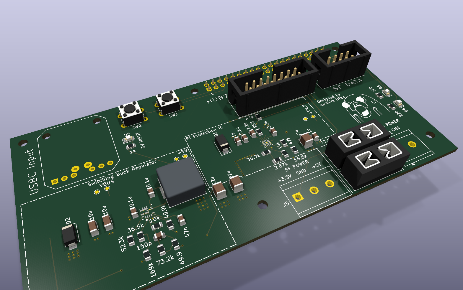
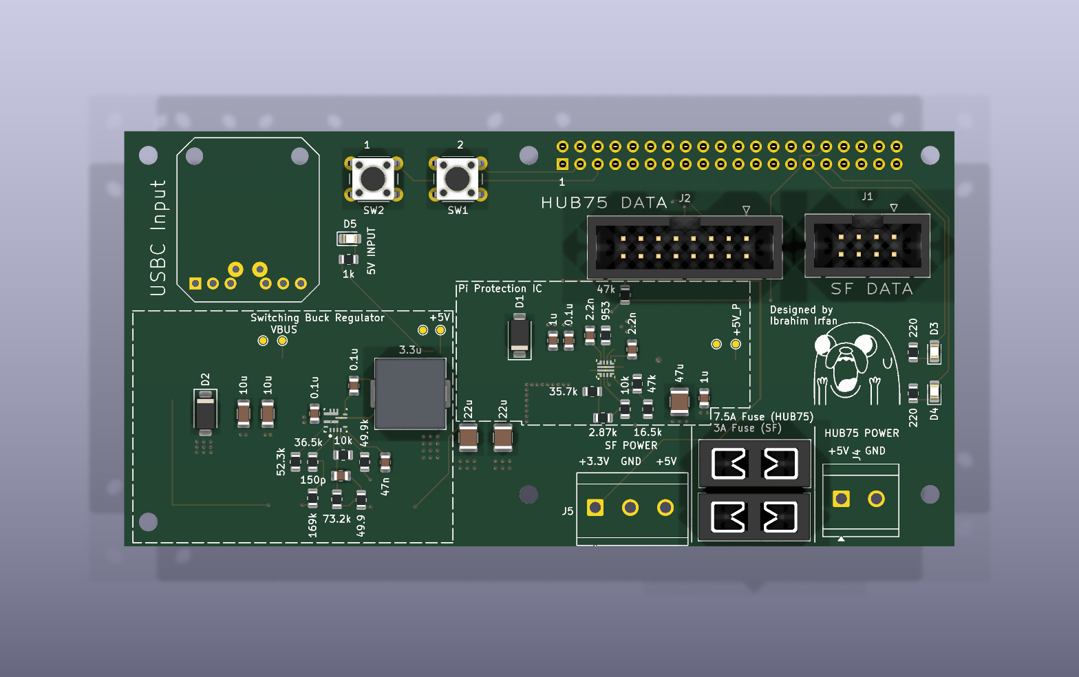
ControlBoard is an open-source printed circuit board by itsmeibii, from the itsmeibii/SplitFlap-Control-Board repository on GitHub. It is a 2-layer board of 120 × 60 mm with 62 parts on 57 nets, routed with 228 tracks and 87 vias.
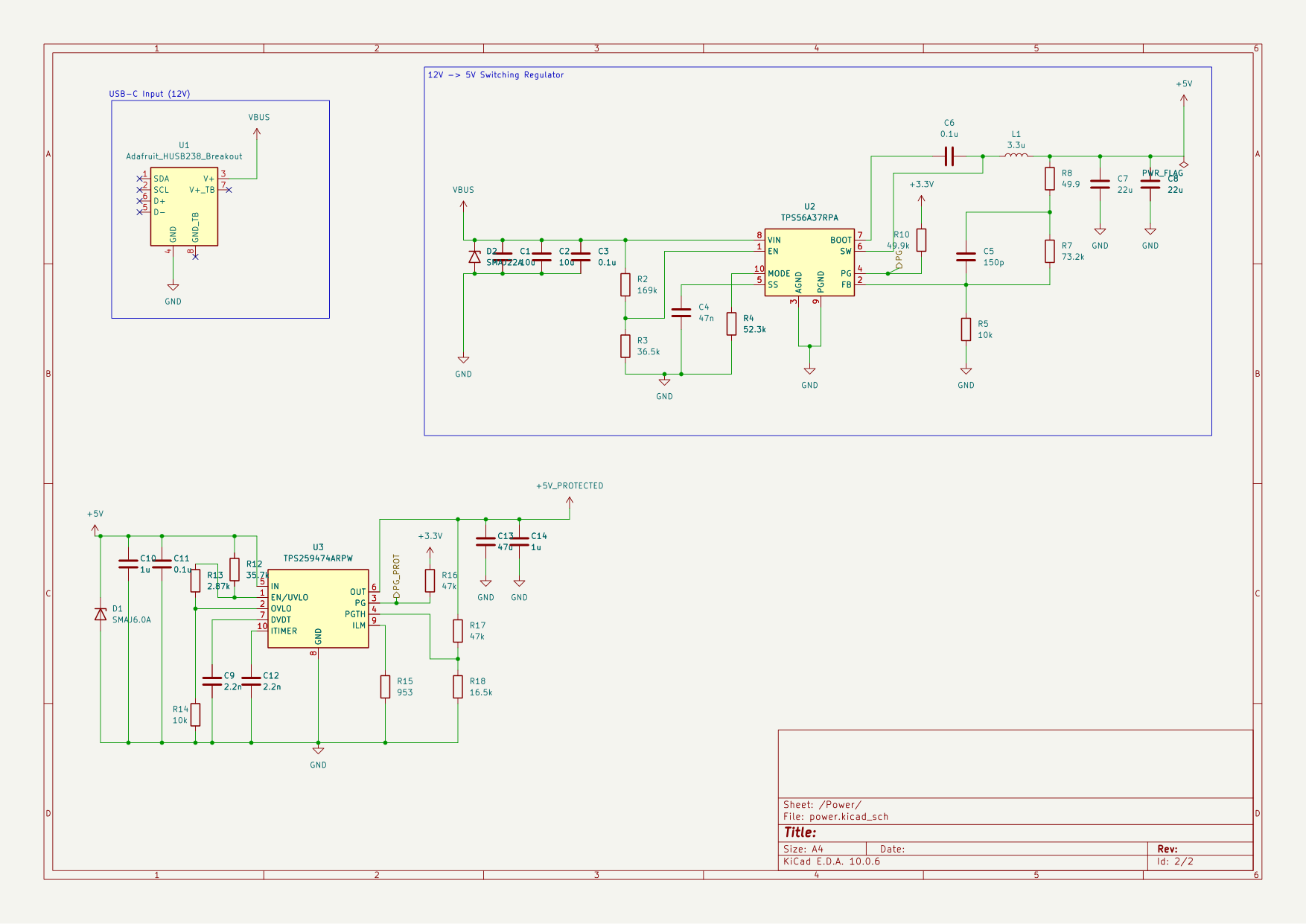
It is built around the TPS56A37RPAR, TPS259474ARPW and LTST-C170KGKT, with the LTST-C170KRKT, LTST-C170TBKT and SMAJ22A among its other parts. Its parts include 17 resistors, 14 capacitors, 5 diodes, 5 connectors and 3 ICs. It belongs with the power and lEDs and displays boards of this library.


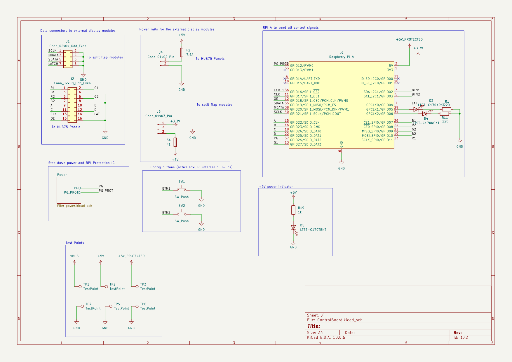
A Raspberry Pi 4 controller board for a split-flap display with HUB75 LED matrix panels. One USB-C PD cable powers the Pi, the split-flap motor drivers and the LED panels.
| Path | Contents |
|---|---|
control board/ControlBoard/ | KiCad 10 project (schematic, PCB, custom symbols/footprints) |
control board/ControlBoard/fab/ | JLCPCB gerbers, assembly files, DigiKey BOM |
housing/ | Enclosure: CadQuery scripts, STEP and STL files |
pi/ | Raspberry Pi smoke test for the Chainlink driver |
hub_75_test/ | HUB75 LED panel test firmware (Arduino + ESP-IDF) |
docs/ | Schematic PDF and renders |
| Top | Bottom |
|---|---|
 | 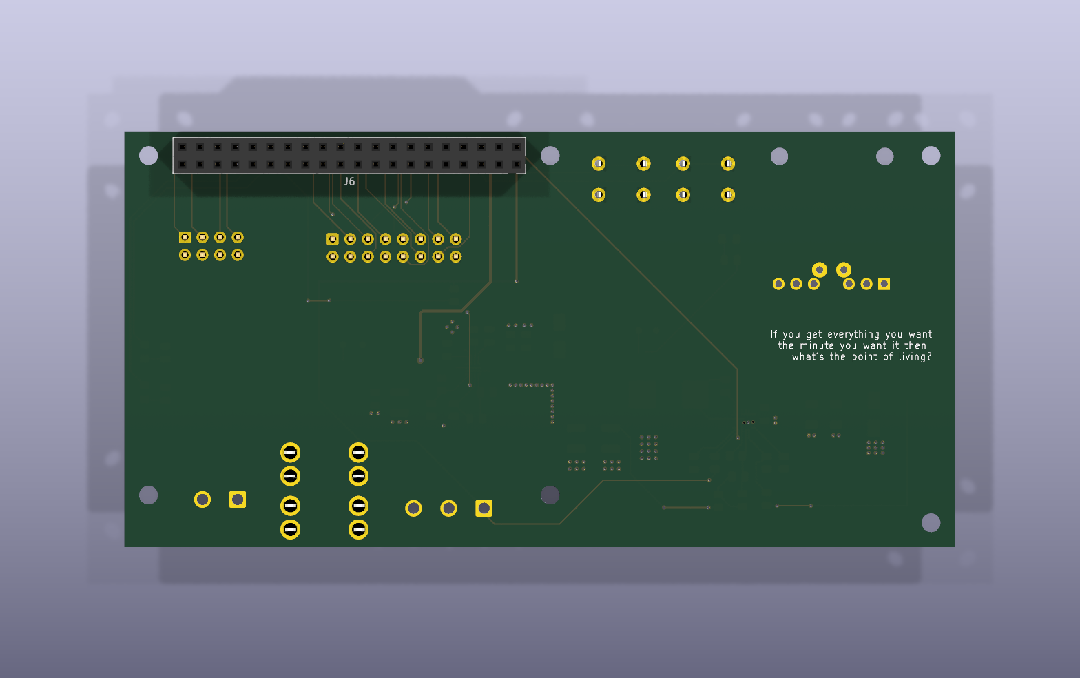 |
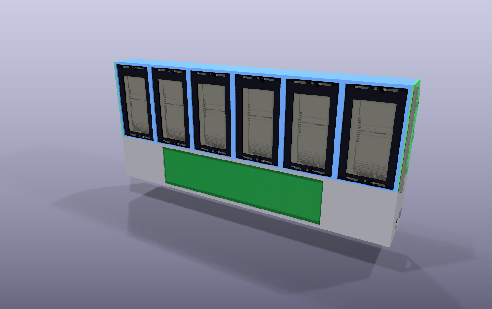
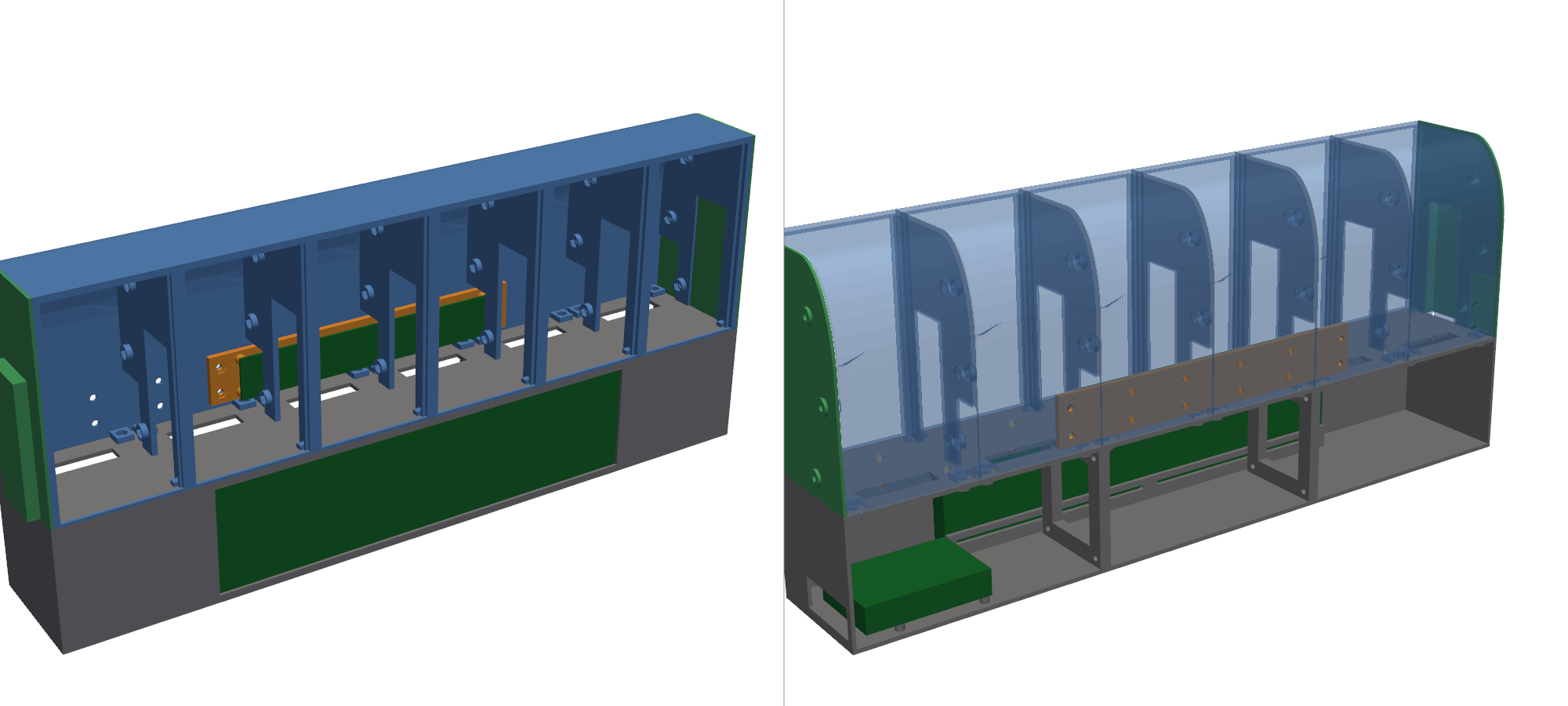
The split-flap mechanism and driver boards come from scottbez1/splitflap. This repo contains only the control board and enclosure I designed for it.
| Qty | Value | Footprint | References |
|---|---|---|---|
| 6 | MountingHole_2.7mm_M2.5 | MountingHole_2.7mm_M2.5 | H1, H2, H3, H4, H5, H6 |
| 6 | TestPoint | TestPoint:TestPoint_Pad_D1.0mm | TP1, TP2, TP3, TP4, TP5, TP6 |
| 3 | 0.1u | Capacitor_SMD:C_0805_2012Metric | C3, C6, C11 |
| 2 | 10k | Resistor_SMD:R_0805_2012Metric | R5, R14 |
| 2 | 10u | Capacitor_SMD:C_1206_3216Metric | C1, C2 |
| 2 | 1u | Capacitor_SMD:C_0805_2012Metric | C10, C14 |
| 2 | 2.2n | Capacitor_SMD:C_0805_2012Metric | C9, C12 |
| 2 | 220 | Resistor_SMD:R_0805_2012Metric | R1, R11 |
| 2 | 22u | Capacitor_SMD:C_1210_3225Metric | C7, C8 |
| 2 | 47k | Resistor_SMD:R_0805_2012Metric | R16, R17 |
| 2 | SW_Push | Button_Switch_THT:SW_PUSH_6mm | SW1, SW2 |
| 1 | 150p | Capacitor_SMD:C_0805_2012Metric | C5 |
| 1 | 16.5k | Resistor_SMD:R_0805_2012Metric | R18 |
| 1 | 169k | Resistor_SMD:R_0805_2012Metric | R2 |
| 1 | 1k | Resistor_SMD:R_0805_2012Metric | R19 |
| 1 | 2.87k | Resistor_SMD:R_0805_2012Metric | R13 |
| 1 | 3.3u | Inductor_SMD:L_Wuerth_HCI-1050 | L1 |
| 1 | 35.7k | Resistor_SMD:R_0805_2012Metric | R12 |
| 1 | 36.5k | Resistor_SMD:R_0805_2012Metric | R3 |
| 1 | 3A | ControlBoard:Fuseholder_Blade_Mini_Keystone_3568 | F1 |
| 1 | 47n | Capacitor_SMD:C_0805_2012Metric | C4 |
| 1 | 47u | Capacitor_SMD:C_1210_3225Metric | C13 |
| 1 | 49.9 | Resistor_SMD:R_0805_2012Metric | R8 |
| 1 | 49.9k | Resistor_SMD:R_0805_2012Metric | R10 |
| 1 | 52.3k | Resistor_SMD:R_0805_2012Metric | R4 |
| 1 | 7.5A | ControlBoard:Fuseholder_Blade_Mini_Keystone_3568 | F2 |
| 1 | 73.2k | Resistor_SMD:R_0805_2012Metric | R7 |
| 1 | 953 | Resistor_SMD:R_0805_2012Metric | R15 |
| 1 | Adafruit_HUSB238_Breakout | Adafruit_HUSB238:Adafruit_HUSB238_Breakout | U1 |
| 1 | Conn_01x02_Pin | TerminalBlock_CUI:TerminalBlock_CUI_TB007-508-02_1x02_P5.08mm_Horizontal | J4 |
| 1 | Conn_01x03_Pin | TerminalBlock_CUI:TerminalBlock_CUI_TB007-508-03_1x03_P5.08mm_Horizontal | J5 |
| 1 | Conn_02x04_Odd_Even | Connector_IDC:IDC-Header_2x04_P2.54mm_Vertical | J1 |
| 1 | Conn_02x08_Odd_Even | Connector_IDC:IDC-Header_2x08_P2.54mm_Vertical | J2 |
| 1 | LTST-C170KGKT | LED_SMD:LED_0805_2012Metric_Pad1.15x1.40mm_HandSolder | D4 |
| 1 | LTST-C170KRKT | LED_SMD:LED_0805_2012Metric_Pad1.15x1.40mm_HandSolder | D3 |
| 1 | LTST-C170TBKT | LED_SMD:LED_0805_2012Metric_Pad1.15x1.40mm_HandSolder | D5 |
| 1 | Logo_Jake | ControlBoard:Logo_Jake_Silkscreen_12mm | LOGO1 |
| 1 | Raspberry_Pi_4 | Connector_PinSocket_2.54mm:PinSocket_2x20_P2.54mm_Vertical | J6 |
| 1 | SMAJ22A | Diode_SMD:D_SMA | D2 |
| 1 | SMAJ6.0A | Diode_SMD:D_SMA | D1 |
| 1 | TPS259474ARPW | ControlBoard:Texas_RPW0010A_VQFN-HR-10_2x2mm_P0.475mm | U3 |
| 1 | TPS56A37RPA | ControlBoard:Texas_RPA0010A_VQFN-HR-10_3x3mm_P0.5mm | U2 |
It measures 120 × 60 mm and has 2 copper layers, 1.6 mm thick.
62 parts, built around the TPS56A37RPAR, TPS259474ARPW, LTST-C170KGKT and LTST-C170KRKT. The full list of its parts is on this page, with links to each part's symbol and footprint where PCBKit's library has them.
From the itsmeibii/SplitFlap-Control-Board repository on GitHub, at the commit this page was made from: the board is control board/ControlBoard/ControlBoard.kicad_pcb and its schematic control board/ControlBoard/ControlBoard.kicad_sch. PCBKit opens the board in the browser, with nothing to install.
Its repository states no licence, so its author keeps all rights: ask itsmeibii before reusing the design.

SushantSaroch13/ESP32-RS485-Lipo_Battery
A compact ESP32-C3 based embedded controller board designed for IoT and industrial communication applications. The board integrates USB connectivity, external flash memory, RS-485 communication, and Li-Ion battery…


Raghav9git/ESP-32-IoT-PCB-Board-
A compact 4-layer IoT development board built around the ESP32-C3, integrating environmental sensing, local storage, USB-C power with LiPo battery management, and a programming/debug interface on a single board.

DLaxV-Community-Projects-Hub/Open-Shot-Clock
Build your own DIY Shot Clock

olexsu/inos-rev-a-robotics-controller
INOS Rev A — CAN-based robotic arm controller designed as a real-time motion-control node for NVIDIA Jetson robotics systems.

