2 layers30 × 61.3 mm

 isotope-engineering/PiMod-Zero39
Raspberry Pi Zero RF Modulator Hat
PiMod Zero is an open-source printed circuit board by isotope-engineering, from the isotope-engineering/PiMod-Zero repository on GitHub. It is a 2-layer board of 65 × 30 mm with 47 parts on 62 nets, routed with 150 tracks and 8 vias.
It is built around the NJM2519AM#. Its parts include 19 capacitors, 15 resistors, 3 connectors, 2 inductors and 1 IC.
The PiMod Zero brings old tech back to life by allowing a Raspberry Pi Zero to display color or B&W video—and play audio—on vintage televisions. It provides a super-compact way to watch old movies, play retro games, present digital art, or navigate your operating system using any television that receives standard NTSC broadcasts on VHF channels 2 and 3 (55.25 MHz and 61.25 MHz).
In the past, you would have needed a cumbersome RF modulator box to adapt the HDMI signal from a Pi Zero. Now, with this convenient HAT snapped on top of your Pi Zero, no additional dongles are required. In fact, once the Pi is powered up, the only other cable you need is a piece of coax to connect the PiMod Zero to your TV.
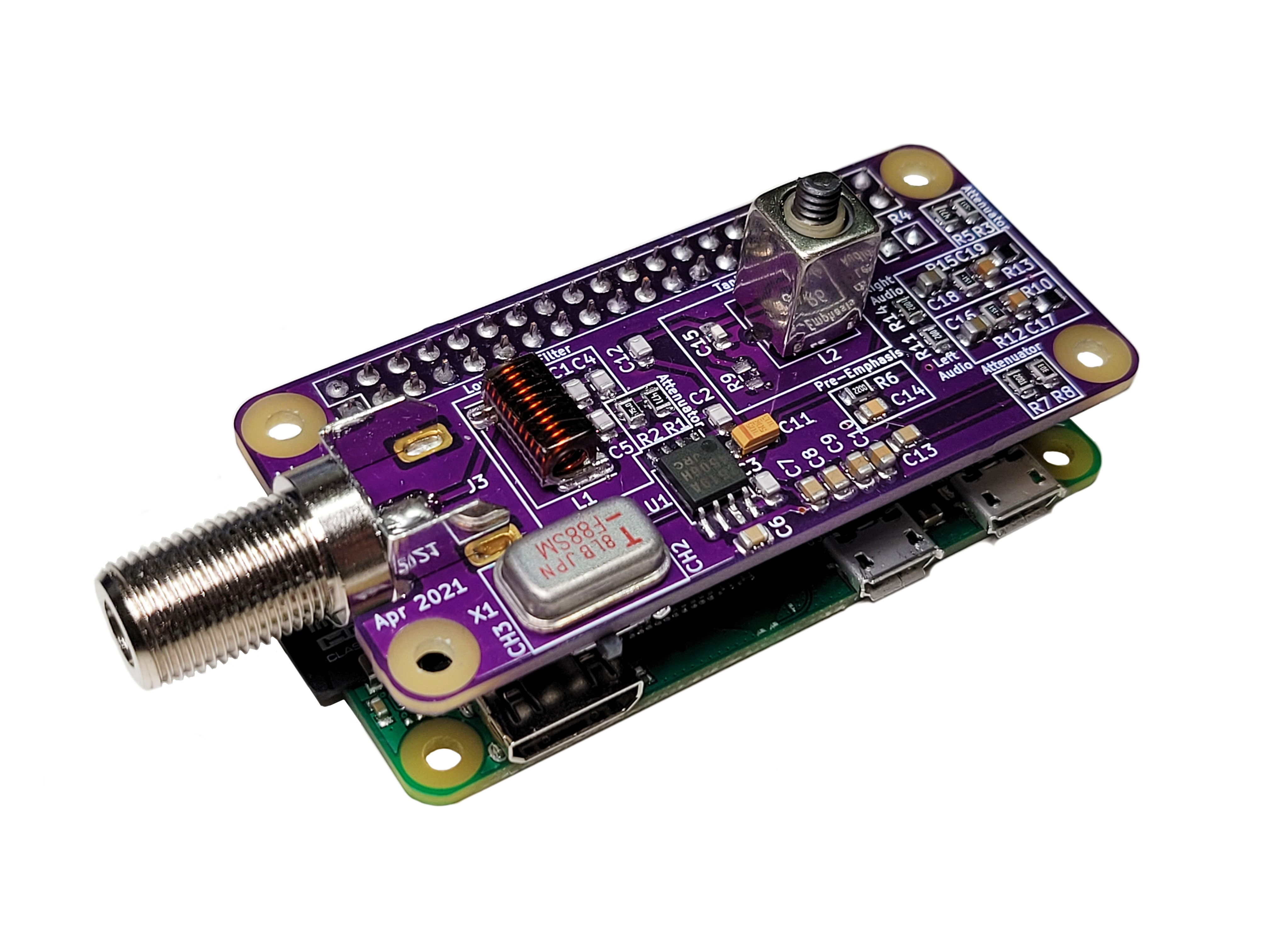
Check out the Setup directory.
| Qty | Value | Footprint | References |
|---|---|---|---|
| 4 | RPi_Hat:RPi_Hat_Mounting_Hole | , , , | |
| 4 | 0.1u | Capacitor_SMD:C_0805_2012Metric | C6, C7, C8, C13 |
| 2 | 10k | Resistor_SMD:R_0805_2012Metric | R11, R14 |
| 2 | 10u | Capacitor_SMD:C_0805_2012Metric | C16, C18 |
| 2 | 150 | Resistor_SMD:R_0805_2012Metric | R12, R15 |
| 2 | 1n | Capacitor_SMD:C_0805_2012Metric | C3, C12 |
| 2 | 1u | Capacitor_SMD:C_0805_2012Metric | C9, C10 |
| 2 | 24p | Capacitor_SMD:C_0805_2012Metric | C4, C5 |
| 2 | 270 | Resistor_SMD:R_0805_2012Metric | R10, R13 |
| 2 | 33n | Capacitor_SMD:C_0805_2012Metric | C17, C19 |
| 2 | 470 | Resistor_SMD:R_0805_2012Metric | R1, R5 |
| 2 | 75 | Resistor_SMD:R_0805_2012Metric | R2, R4 |
| 1 | 100p | Capacitor_SMD:C_0805_2012Metric | C2 |
| 1 | 133n | KiCad-Library-master:Wurth_WE_Inductor_744918213 | L1 |
| 1 | 1u | Capacitor_SMD:C_1206_3216Metric | C11 |
| 1 | 220 | Resistor_SMD:R_0805_2012Metric | R6 |
| 1 | 2K | Resistor_SMD:R_0805_2012Metric | R7 |
| 1 | 30K | Resistor_SMD:R_0805_2012Metric | R8 |
| 1 | 360p | Capacitor_SMD:C_0805_2012Metric | C14 |
| 1 | 510 | Resistor_SMD:R_0805_2012Metric | R3 |
| 1 | 68p | Capacitor_SMD:C_0805_2012Metric | C15 |
| 1 | 6p | Capacitor_SMD:C_0805_2012Metric | C1 |
| 1 | Amphenol 531-40101 | rf_modulator:Amphenol-531-40101 | J3 |
| 1 | F88SM | rf_modulator:F88SM | X1 |
| 1 | LOGO | rf_modulator:modulator_art | G*** |
| 1 | LTRIM | rf_modulator:Coilcraft-Slot-7-Inductor | L2 |
| 1 | NJM2519A | Package_SO:SOIC-8_5.23x5.23mm_P1.27mm | U1 |
| 1 | Pi Video | Connector_PinHeader_2.54mm:PinHeader_1x02_P2.54mm_Vertical | J2 |
| 1 | RPi_GPIO | Connector_PinHeader_2.54mm:PinHeader_2x20_P2.54mm_Vertical | J1 |
| 1 | R_US | Resistor_SMD:R_0805_2012Metric | R9 |
| 1 | SW_SPDT | Button_Switch_SMD:SW_SPDT_PCM12 | SW1 |
It measures 65 × 30 mm and has 2 copper layers, 1.6 mm thick.
47 parts, built around the NJM2519AM#. The full list of its parts is on this page, with links to each part's symbol and footprint where PCBKit's library has them.
From the isotope-engineering/PiMod-Zero repository on GitHub, at the commit this page was made from: the board is hardware/PiMod Zero.kicad_pcb. PCBKit opens the board in the browser, with nothing to install.
Its repository states no licence, so its author keeps all rights: ask isotope-engineering before reusing the design.


VoronDesign/Voron-Hardware
Cool Hardware designed by the Voron Design group

hackclub/OnBoard
💡 Join 1,000 teenagers and make your first PCB with a $100 grant!


FrameworkComputer/InputModules
Reference designs and documentation for the Input Module system in the Framework Laptop 16