2 layers80 × 50 mm

 iowlabs/phecda1
phecda reposiroty
Phecda board is an open-source printed circuit board by iowlabs, from the iowlabs/phecda repository on GitHub. It is a 2-layer board of 100 × 85 mm with 92 parts on 108 nets, routed with 708 tracks and 244 vias.
It is built around the CH340C, ESP32-WROOM-32D and AP2112K-3.3, with the RFM95W-915S2, RV-8803-C7 and BSS138 among its other parts. Its parts include 24 resistors, 17 connectors, 11 capacitors, 10 crystals and 5 ICs. It belongs with the ESP32 boards of this library.


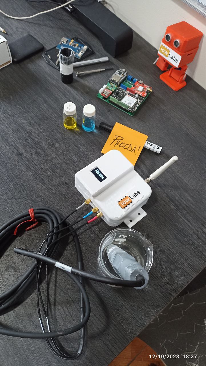
Phecda is a device that allows measuring different electrochemical variables such as pH, ORP, temperature, dissolved oxygen and electroconductivity, based on sensors developed by Atlas Scientific. A on board ESP32 microcontroller manages data acquisition and sending tasks. It count with an rfm95 LoRa module, ideal for integration with LoRa or LoRaWan networks.
Phecda can adapt to a wide variety of BT, WiFi or LoRa based IoT applications. A micro SD adapter and an onboard RTC implement data logger functionality for offline information collection. An OLED screen allows you to view the data of interest in real time.
IoT,Ph, Environmental measurement, LoRa, AtlasScientific, datalogger.
| Licenses | OSHW certification |
|---|---|
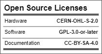 |  |
The PCB was designed in KiCad7 stable realease and additional components from the official iowLabs library.
The pcb can be powered via USB or through the screw terminal block J7 connector. Jumper J2 must be shorted to enable power on the board. Or it can connect to an external On/OFF button.
To have compatibility with different probes, the board has SMA connectors J13 to J17 or alternatively the terminal blocks J10, J11 and J12.
The board is based on an ESP32 microcontroller.

| Top view | Bottom view |
|---|---|
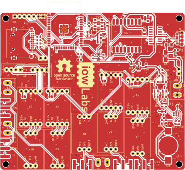 | 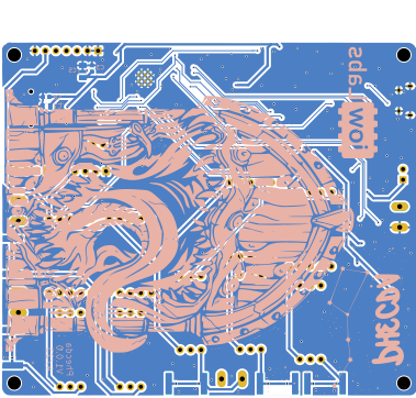 |
The bill of materials with respective references to LCSC part numbers can be found at the following link.
The following table presents a list of references for the probes and reading electronics along with their respective links. These components are left only as a reference since they depend on the application and the type of variables that you want to measure.
| Components | Quantity | Description | link |
|---|---|---|---|
| industrial PH probe | 1 | industrial PH, ORP y RTC probe | AtlasScientific oficial website |
| OD probe | 1 | Lab Grade Dissolved Oxygen Probe | AtlasScientific oficial website |
| EC probe | 1 | Conductivity Probe K 0.1 | AtlasScientific oficial website |
| Ezo ph | 1 | Readout para la sonda de EC | AtlasScientific oficial website |
| Ezo orp | 1 | Readout para la sonda de ORP | AtlasScientific oficial website |
| Ezo RTC | 1 | Readout para la sonda de RTC | AtlasScientific oficial website |
| Ezo OD | 1 | Readout para la sonda de OD | AtlasScientific oficial website |
| Ezo EC | 1 | Readout para la sonda de EC | AtlasScientific oficial website |
| Ezo IVI | 4 | Basic EZO Inline Voltage Isolator | AtlasScientific oficial website |
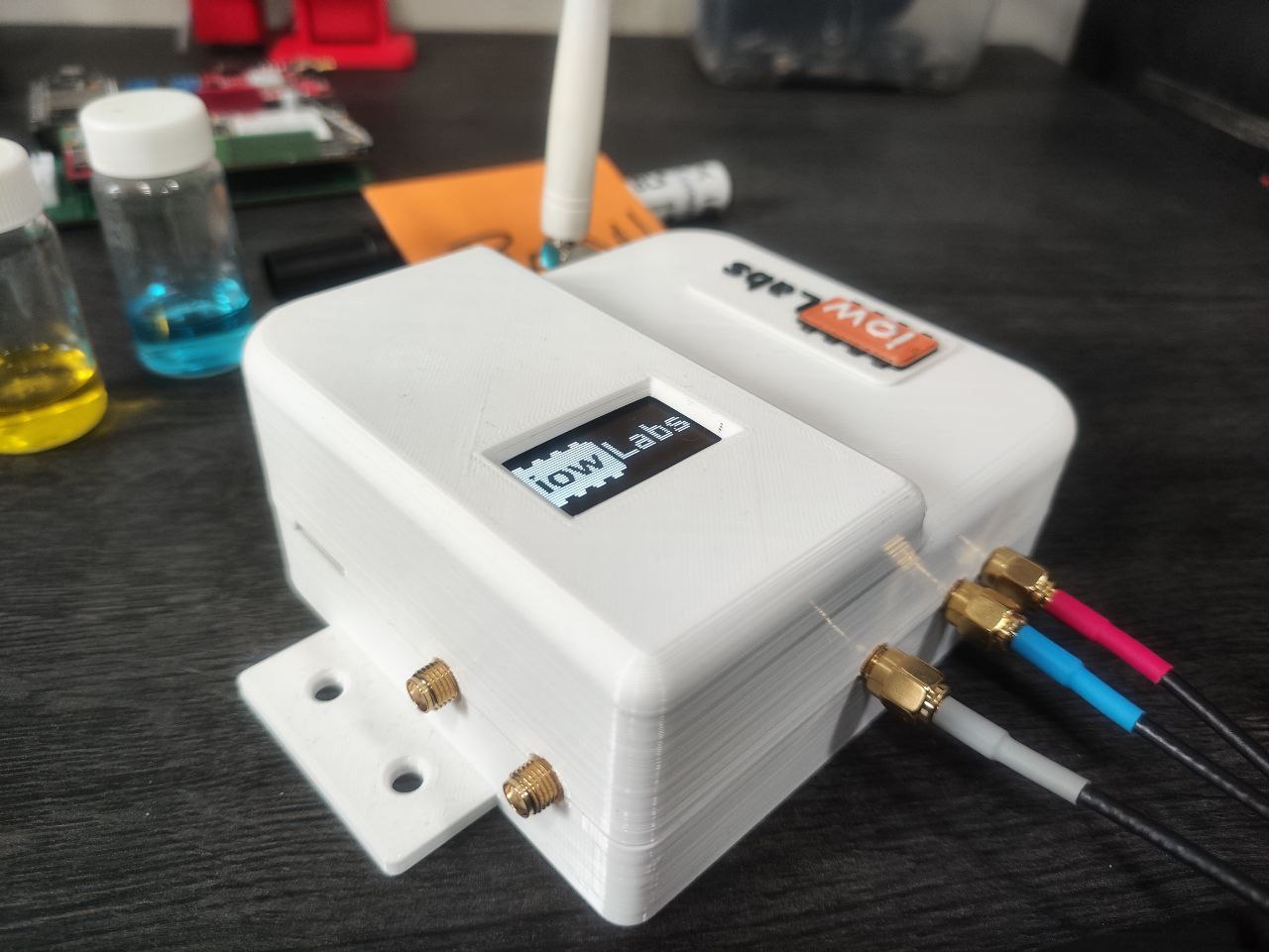
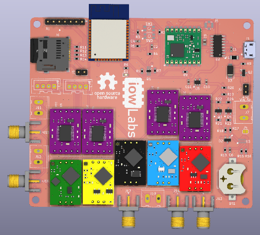
For versions with laboratory applications or controlled climate conditions, a printable case was designed in PLA or ABS using Fusion360.
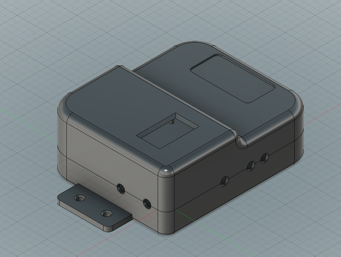
The design is a simple case composed of two parts that allows the OLED screen to be incorporated and exposes the SMA connectors for the probes, protecting the internal electronics.
| Cover | Base |
|---|---|
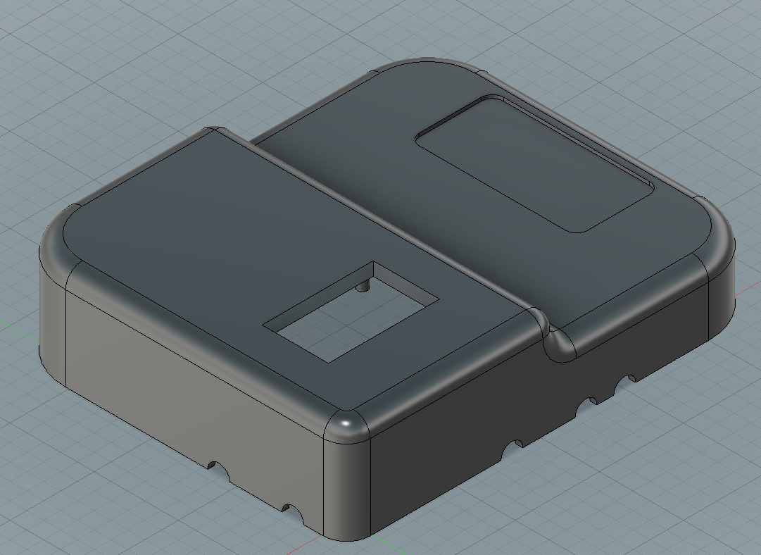 | 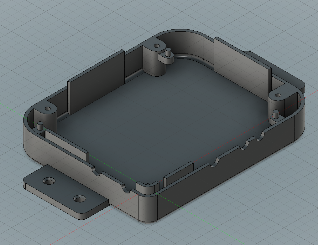 |
To power the device, the design consider a powerbank located at the bottom. The assembly of the two pieces is carried out using 3 M3 screws that are screwed from the bottom of the base.
Editable files and display plans can be found in directorio.
The PCB design allows it to fit commercial project enclosures with IP65 standards or higher for outdoor or harsh weather applications.
The developed firmware represents a collection of libraries and drivers for the board's dependencies.
This collection of useful functions is implemented in the iowPhecda library. However, due to the flexibility of the design, it is possible to load a wide variety of code based on other supported libraries.
The firmware was developed using PlatformIO; however, usage examples were generated for [Arduino IDE] (https://www.arduino.cc/en/software).
| Folder | Description |
|---|---|
| firmware/phecda_project | The complete project compiled in its last version. |
| firmware/examples | Arduino compatible example codes . |
| firmware/src | The source files of the library made for phecda. |
Except for the uSD_iow library which is available in the official iowlabs repository, all other libraries used are available from the official Arduino and PlatformIO library manager.
| File | Description |
|---|---|
| simple_version.ino | Collect the data from the pH, ORP and temperature sensors, and displays it on the screen. Print the collected data in json format through the serial monitor. |
| low_energy_version.ino | Adds a low-power mode to the simple_version code |
| lora_version.ino | Activate the LoRa module and send a message in json format. |
| mqtt_version.ino | This is an example of reading the data and sending it via MQTT to a pre-established broker. |
| Qty | Value | Footprint | References |
|---|---|---|---|
| 5 | 100n | Capacitor_SMD:C_0603_1608Metric | C1, C2, C3, C4, C8 |
| 5 | 10K | Resistor_SMD:R_0603_1608Metric | R1, R4, R5, R7, R8 |
| 5 | 10k | Resistor_SMD:R_0603_1608Metric | R9, R21, R22, R23, R24 |
| 5 | 3.3k | Resistor_SMD:R_0603_1608Metric | R10, R11, R12, R13, R14 |
| 5 | Conn_Coaxial | Connector_Coaxial:SMA_Amphenol_132289_EdgeMount | J13, J14, J15, J16, J17 |
| 5 | Ezp-generic | IoWLabsModules:Ezo_generic | X6, X7, X8, X9, X10 |
| 4 | Ezo_ivi_iso | IoWLabsModules:Ezo_iso | X2, X3, X4, X5 |
| 4 | HDR-2x1 | IoWLabsConnectors:Tb-2x1-5p-TH-V | J7, J10, J11, J12 |
| 4 | MountingHole | MountingHole:MountingHole_2.2mm_M2 | H1, H2, H3, H4 |
| 4 | SolderJumper_2_Open | Jumper:SolderJumper-2_P1.3mm_Open_RoundedPad1.0x1.5mm | JP1, JP2, JP3, JP4 |
| 2 | 100k | Resistor_SMD:R_0603_1608Metric | R15, R16 |
| 2 | 1u | Capacitor_SMD:C_0603_1608Metric | C10, C11 |
| 2 | 2.2k | Resistor_SMD:R_0603_1608Metric | R17, R18 |
| 2 | 200 | Resistor_SMD:R_0603_1608Metric | R2, R3 |
| 2 | 4.7k | Resistor_SMD:R_0603_1608Metric | R19, R20 |
| 2 | BSS138 | Package_TO_SOT_SMD:SOT-23 | Q3, Q4 |
| 2 | HDR-4x1 | Connector_JST:JST_XA_B04B-XASK-1_1x04_P2.50mm_Vertical | J8, J9 |
| 2 | LOGO | IoWLabsLogos:IoWLabsLogo | G***, G*** |
| 2 | SW_DIP_x02 | IoWLabs:SMD_SWITCH | SW1, SW2 |
| 1 | 10n | Capacitor_SMD:C_0603_1608Metric | C6 |
| 1 | 10u | Capacitor_SMD:C_1206_3216Metric | C5 |
| 1 | 10u | Capacitor_SMD:C_0805_2012Metric | C7 |
| 1 | 330 | Resistor_SMD:R_0603_1608Metric | R6 |
| 1 | 4.7u | Capacitor_SMD:C_0805_2012Metric | C9 |
| 1 | AP2112K-3.3 | Package_TO_SOT_SMD:SOT-23-5 | U5 |
| 1 | BAS70-05 | Package_TO_SOT_SMD:SOT-23 | D2 |
| 1 | Battery_Cell | Battery:BatteryHolder_Keystone_3000_1x12mm | BT1 |
| 1 | CH340C | Package_SO:SOIC-16_3.9x9.9mm_P1.27mm | U2 |
| 1 | Conn_01x02 | Jumper:SolderJumper-2_P1.3mm_Open_RoundedPad1.0x1.5mm | J4 |
| 1 | Conn_Coaxial | Connector_Coaxial:U.FL_Molex_MCRF_73412-0110_Vertical | J5 |
| 1 | D_Schottky | Diode_SMD:D_SMA | D3 |
| 1 | E32 | Connector_PinHeader_2.54mm:PinHeader_1x07_P2.54mm_Vertical | X1 |
| 1 | ESP32-WROOM-32D | RF_Module:ESP32-WROOM-32 | U1 |
| 1 | FUSE | Fuse:Fuse_1206_3216Metric | F1 |
| 1 | HDR-2x1 | Connector_PinHeader_2.54mm:PinHeader_1x02_P2.54mm_Vertical | J3 |
| 1 | LED | LED_SMD:LED_0603_1608Metric | D1 |
| 1 | LOGO | IoWLabsLogos:phecda | G*** |
| 1 | LOGO | IoWLabsLogos:ursa_major | G*** |
| 1 | LOGO | IoWLabsLogos:mimictest | G*** |
| 1 | ON OFF | Connector_PinHeader_2.54mm:PinHeader_1x02_P2.54mm_Vertical | J2 |
| 1 | Q_Dual_NPN_NPN_BRT_E1B1C2E2B2C1 | Package_TO_SOT_SMD:SOT-363_SC-70-6_Handsoldering | Q1 |
| 1 | Q_PMOS_GSD | Package_TO_SOT_SMD:SOT-23 | Q2 |
| 1 | RFM95W-915S2 | RF_Module:HOPERF_RFM9XW_SMD | U4 |
| 1 | RV-8803 | IoWLabs:SON-8 | U3 |
| 1 | USB_B_Micro | Connector_USB:USB_Micro-B_Amphenol_10118194_Horizontal | J1 |
| 1 | ~ | IoWLabsConnectors:microSD_push_push | J6 |
The 91 most common of 92 parts.
It measures 100 × 85 mm and has 2 copper layers, 1.6 mm thick.
92 parts, built around the CH340C, ESP32-WROOM-32D, AP2112K-3.3 and RFM95W-915S2. The full list of its parts is on this page, with links to each part's symbol and footprint where PCBKit's library has them.
From the iowlabs/phecda repository on GitHub, at the commit this page was made from: the board is hardware/PCB/Phecda_board.kicad_pcb and its schematic hardware/PCB/Phecda_board.kicad_sch. PCBKit opens the board in the browser, with nothing to install.
Its repository states no licence, so its author keeps all rights: ask iowlabs before reusing the design.


wenzel-lab/syringe-pumps-and-controller
Design of 3d printable syringe pumps and dual controller.


jeremypoulter/SmartishNight
Electronics for a ESP32/NeoPixel based nightlight

yogesh8441/ESP32-CUSTOM-DEVELOPMENT-BOARD
A custom-designed ESP32-WROOM-32D Development Board developed using KiCad 10. This project demonstrates the complete PCB design workflow, including schematic design, PCB layout, routing, ground plane implementation…