Skip to the content
2 layers26.7 × 50.8 mmAdapter, the printed circuit board in 3D

Rodeostat design files, software and firmware

Size
26.7 × 50.8 mm
Copper layers
2
Thickness
1.6 mm
Parts
8
Nets
9
Pads
31
Tracks, vias
50, 0
Routed
Yes
KiCad
KiCad 3
Created
20 Jun 2020
Updated
29 Oct 2026

Overview

Adapter is an open-source printed circuit board by iorodeo, from the iorodeo/potentiostat repository on GitHub, published under the CC-BY-4.0 licence. It is a 2-layer board of 26.7 × 50.8 mm with 8 parts on 9 nets, routed with 50 tracks and 0 vias.

Its parts include 7 switches and 1 connector. It belongs with the interfaces and adapters boards of this library.

README

README.md

IO Rodeo Rodeostat

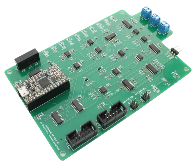
alt text

Hardware design, firmware and software for IO Rodeo's Rodeostat Potentiostat.

Hardware

  • Designed as a shield for teensy 3.2 development board.
  • 12-bit voltage output with four range settings: +/- 1, 2, 5, 10V
  • 16-bit current measurement with four range settings: +/- 1, 10, 100, 1000 uA ranges
  • Can be programmed over USB using the Arduino IDE (teensyduino).
  • Expansion headers with DIO, analog inputs, UART, I2C, and SPI
  • Schematic

Firmware

  • Implements many standard voltammetric methods including:
    • constant voltage,
    • cyclic voltammetry,
    • sinusoidal voltammetry,
    • linearsweep voltammetry,
    • chronoamperometry,
    • multistep.
  • API for control over USB/Serial using messages in JSON.
  • Easy to extend enabling users to add custom tests.

Libraries

Software

Parts

8
QtyValueFootprintReferences
7CONN_3PIN_ARRAY_3X1K1, K2, K3, K4, K5, K6, K7
1CONN_5X25X2_SHRD_HEADER_FEMALEP1

More from iorodeo/potentiostat

9
  • 2 layers144.8 × 88.9 mmPotentiostat, the printed circuit board in 3D

    Potentiostat

    iorodeo/potentiostat

    Rodeostat design files, software and firmware

    142 parts57CC-BY-4.0
  • 2 layers144.8 × 88.9 mmPotentiostat, the printed circuit board in 3D

    Potentiostat

    iorodeo/potentiostat

    Rodeostat design files, software and firmware

    141 parts57CC-BY-4.0
  • 2 layers144.8 × 88.9 mmPotentiostat, the printed circuit board in 3D

    Potentiostat

    iorodeo/potentiostat

    Rodeostat design files, software and firmware

    99 parts57CC-BY-4.0
  • 2 layers82.6 × 88.9 mmMultiplexer, the printed circuit board in 3D

    Multiplexer

    iorodeo/potentiostat

    Rodeostat design files, software and firmware

    26 parts57CC-BY-4.0
  • 2 layers81.3 × 88.9 mmMultiplexer, the printed circuit board in 3D

    Multiplexer

    iorodeo/potentiostat

    Rodeostat design files, software and firmware

    23 parts57CC-BY-4.0
  • 2 layers82.6 × 88.9 mmMultiplexer, the printed circuit board in 3D

    Multiplexer

    iorodeo/potentiostat

    Rodeostat design files, software and firmware

    22 parts57CC-BY-4.0
  • 2 layers31.8 × 50.8 mmDummy cell, the printed circuit board in 3D

    Dummy cell

    iorodeo/potentiostat

    Rodeostat design files, software and firmware

    9 parts57CC-BY-4.0
  • 2 layers26.7 × 50.8 mmAdapter, the printed circuit board in 3D

    Adapter

    iorodeo/potentiostat

    Rodeostat design files, software and firmware

    3 parts57CC-BY-4.0
  • 2 layers12 × 25 mmSmt dummy cell, the printed circuit board in 3D

    Smt dummy cell

    iorodeo/potentiostat

    Rodeostat design files, software and firmware

    2 parts57CC-BY-4.0

Similar boards

  • 2 layers20.5 × 24.8 mmPi interface, the printed circuit board in 3D

    Pi interface

    opulo-inc/lumenpnp

    The LumenPnP is an open source pick and place machine.

    8 parts3.7k
  • 2 layers59.9 × 25.7 mmBuffer, the printed circuit board in 3D

    Buffer

    hoglet67/RGBtoHDMI

    Bare-metal Raspberry Pi project that provides pixel-perfect sampling of Retro Computer RGB/YUV video and conversion to HDMI

    8 parts1kGPL-3.0
  • 2 layers52 × 12.6 mmUSB, the printed circuit board in 3D

    USB

    shanteacontrols/OpenDeck

    A platform for building interactive control and sensing devices using MIDI and OSC built with Zephyr RTOS.

    8 parts960Apache-2.0
  • 2 layers87.5 × 48.5 mm7 input macropad, the printed circuit board in 3D

    7 input macropad

    hackclub/OnBoard

    💡 Join 1,000 teenagers and make your first PCB with a $100 grant!

    8 parts915
  • 2 layers36.2 × 63.1 mmPicoMemcard pico, the printed circuit board in 3D

    PicoMemcard pico

    dangiu/PicoMemcard

    Emulating PSX Memory Card (or controller) using a Raspberry Pi Pico

    8 parts694GPL-3.0
  • 2 layers36 × 10 mmPCB4-PWR BTN Rev.A, the printed circuit board in 3D

    PCB4-PWR BTN Rev.A

    OLIMEX/DIY-LAPTOP

    Do It Yourself Open Source Hardware and Software Modular Hacker's Friendly Laptop

    8 parts578Apache-2.0

Questions

How big is the Adapter PCB?

It measures 26.7 × 50.8 mm and has 2 copper layers, 1.6 mm thick.

What parts does the Adapter use?

8 parts. The full list of its parts is on this page, with links to each part's symbol and footprint where PCBKit's library has them.

Where can I download the Adapter KiCad files?

From the iorodeo/potentiostat repository on GitHub, at the commit this page was made from: the board is hardware/pcbs/multiplexer_adapters/mux_to_3pin/adapter.kicad_pcb. PCBKit opens the board in the browser, with nothing to install.

Can I use the Adapter design in my own project?

Its repository publishes it under the CC-BY-4.0 licence: you may reuse it on that licence's terms (keep the author's notice, and for a copyleft licence share your changes alike).