2 layers74.1 × 112 mm
 ionutms/Modular_Software_Configurable_IO_PLC
This repository contains a modular KiCad design project for a Software Configurable I/O PLC. The project integrates several advanced components to create a versatile and powerful industrial control solution.
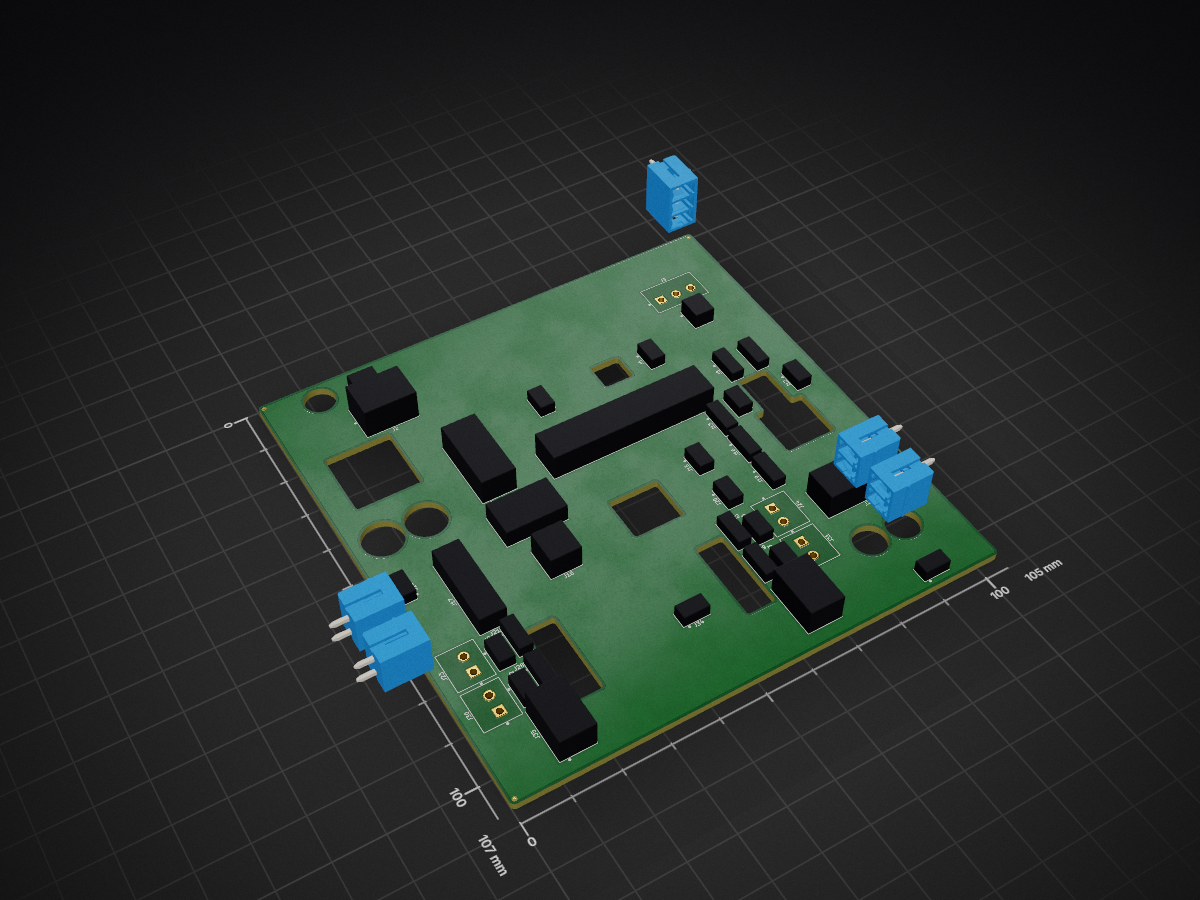
Modular Software Configurable IO PLC is an open-source printed circuit board by ionutms, from the ionutms/Modular_Software_Configurable_IO_PLC repository on GitHub, published under the MIT licence. It is a 4-layer board of 105 × 107 mm with 51 parts on 247 nets.
It is built around the CLP-102-02-G-D-BE, TBP02R2-381-02BE and 8SS1012-Z, with the CLP-103-02-G-D-BE, CLP-114-02-G-D-BE and TBP02R2-381-03BE among its other parts. Its parts include 37 connectors and 1 switch.

This repository contains a modular KiCad design project for a Software Configurable I/O PLC. The project integrates several advanced components to create a versatile and powerful industrial control solution. It features software-configurable analog and digital I/O, single-pair Ethernet with Power over Data Line (PoDL) capabilities, and a robust power architecture.
[!NOTE] This project is provided "as is" and without any warranty, express or implied. For more details, please see the LICENSE file.
This PLC design is built around a combination of high-performance integrated circuits:
modular_software_configurable_io_plc/
├── modular_software_configurable_io_plc.kicad_pro    # Project configuration file
├── modular_software_configurable_io_plc.kicad_sch    # Main schematic file
├── modular_software_configurable_io_plc.kicad_pcb    # PCB layout file
├── fp-lib-table                                      # Footprint library table
├── sym-lib-table                                     # Symbol library table
├── docs/                                             # Documentation files
│   ├── bom/                                          # Bill of Materials
│   │   └── modular_software_configurable_io_plc_ibom.html # Interactive BOM file
│   ├── pictures/                                     # Images and photos
│   │   ├── 1_modular_software_configurable_io_plc_side.png
│   │   ├── 2_modular_software_configurable_io_plc_top.png
│   │   ├── 3_modular_software_configurable_io_plc_bottom.png
│   │   ├── 4_modular_software_configurable_io_plc_left.png
│   │   ├── 5_modular_software_configurable_io_plc_right.png
│   │   ├── 6_modular_software_configurable_io_plc_front.png
│   │   ├── 7_modular_software_configurable_io_plc_back.png
│   │   ├── 8_modular_software_configurable_io_plc_side_exploded_1.png
│   │   ├── 9_modular_software_configurable_io_plc_side_exploded_2.png
│   │   ├── 10_modular_software_configurable_io_plc_side_exploded_3.png
│   │   ├── 11_modular_software_configurable_io_plc_side_enclosure.png
│   │   ├── 12_modular_software_configurable_io_plc_top_enclosure.png
│   │   ├── 13_modular_software_configurable_io_plc_bottom_enclosure.png
│ │ ├── 14_modular_software_configurable_io_plc_left_enclosure.pngThis design provides a comprehensive and modular software-configurable I/O PLC with:
Clone the repository (including submodules):
git clone --recursive https://github.com/ionutms/Modular_Software_Configurable_IO_PLC.gitIf you have already cloned the repository without submodules, initialize them with:
git submodule init
git submodule update
Open the project in KiCad:
modular_software_configurable_io_plc.kicad_pro file.Explore the design:
This project has the following dependencies:
This repository uses KiCAD_Symbols_Generator as a submodule for custom symbol generation.
To initialize the submodule after cloning this repository:
git submodule update --init --recursiveThis project requires the 3D_Models_Vault repository for 3D models.
Clone the 3D models repository:
git clone https://github.com/ionutms/3D_Models_Vault.gitIn KiCad 9, add an environment variable:
Preferences -> Configure Paths...Add to create a new environment variable.KICAD9_3D_MODELS_VAULT3D_Models_Vault repository.This project includes the KiCAD_Symbols_Generator as a submodule, which provides tools for generating KiCad symbols from CSV data files. For more information on using this tool, see the documentation within the submodule's directory.
The docs folder contains:
The following images showcase the PCB design from different perspectives:
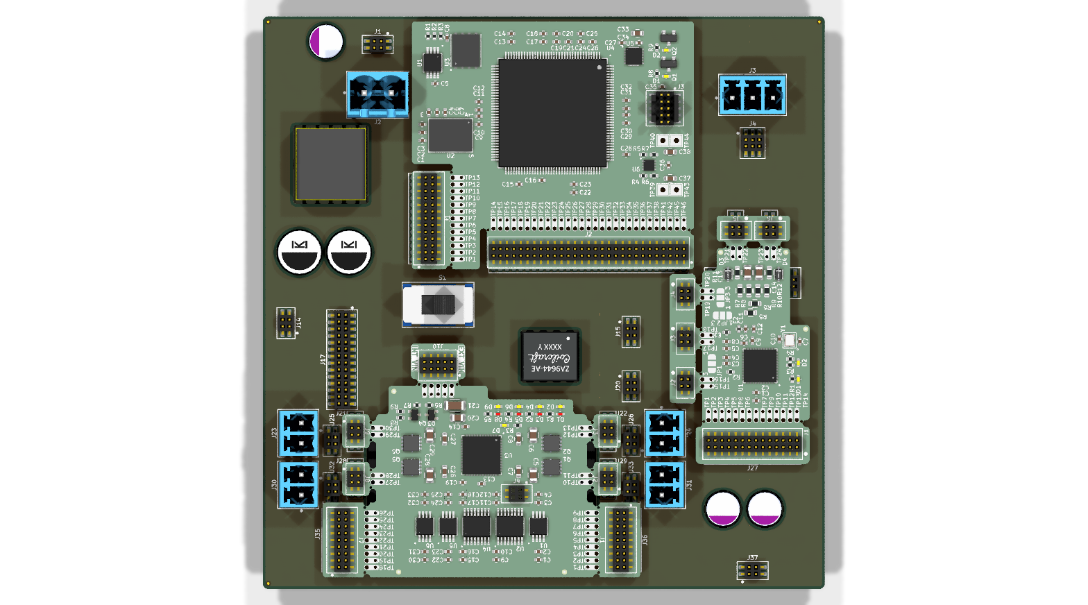 Top View of the PCB
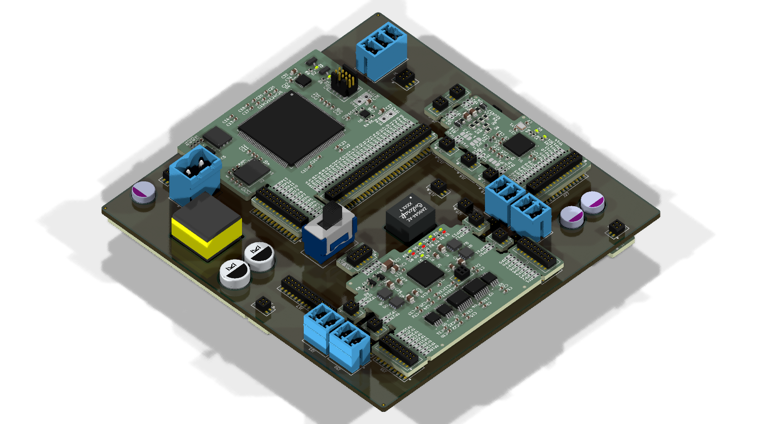 Side View of the PCB
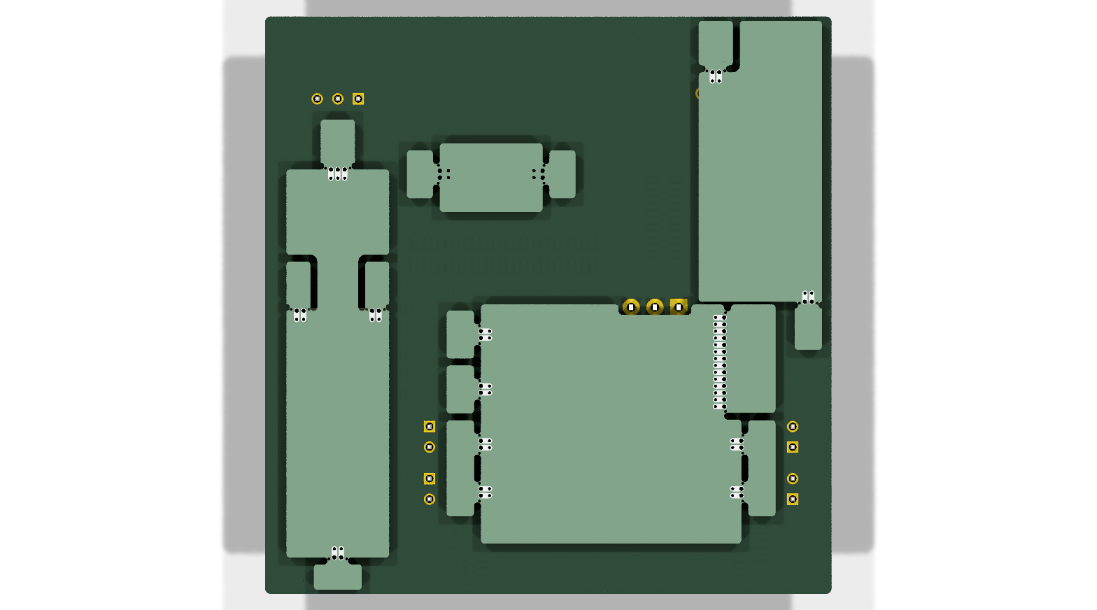 Bottom View of the PCB
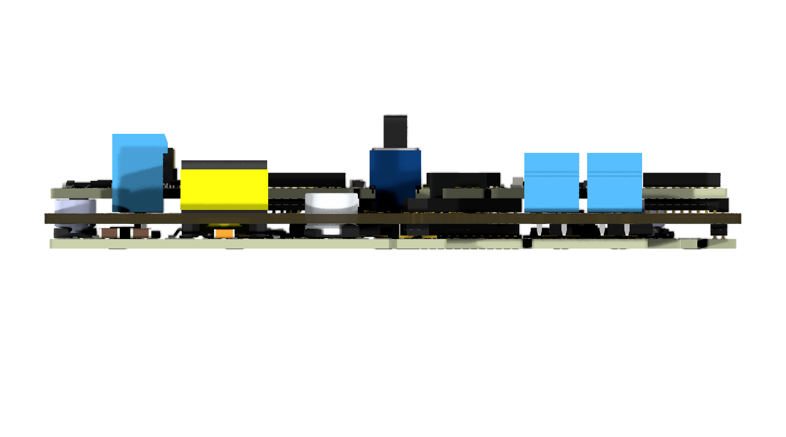 Left View of the PCB
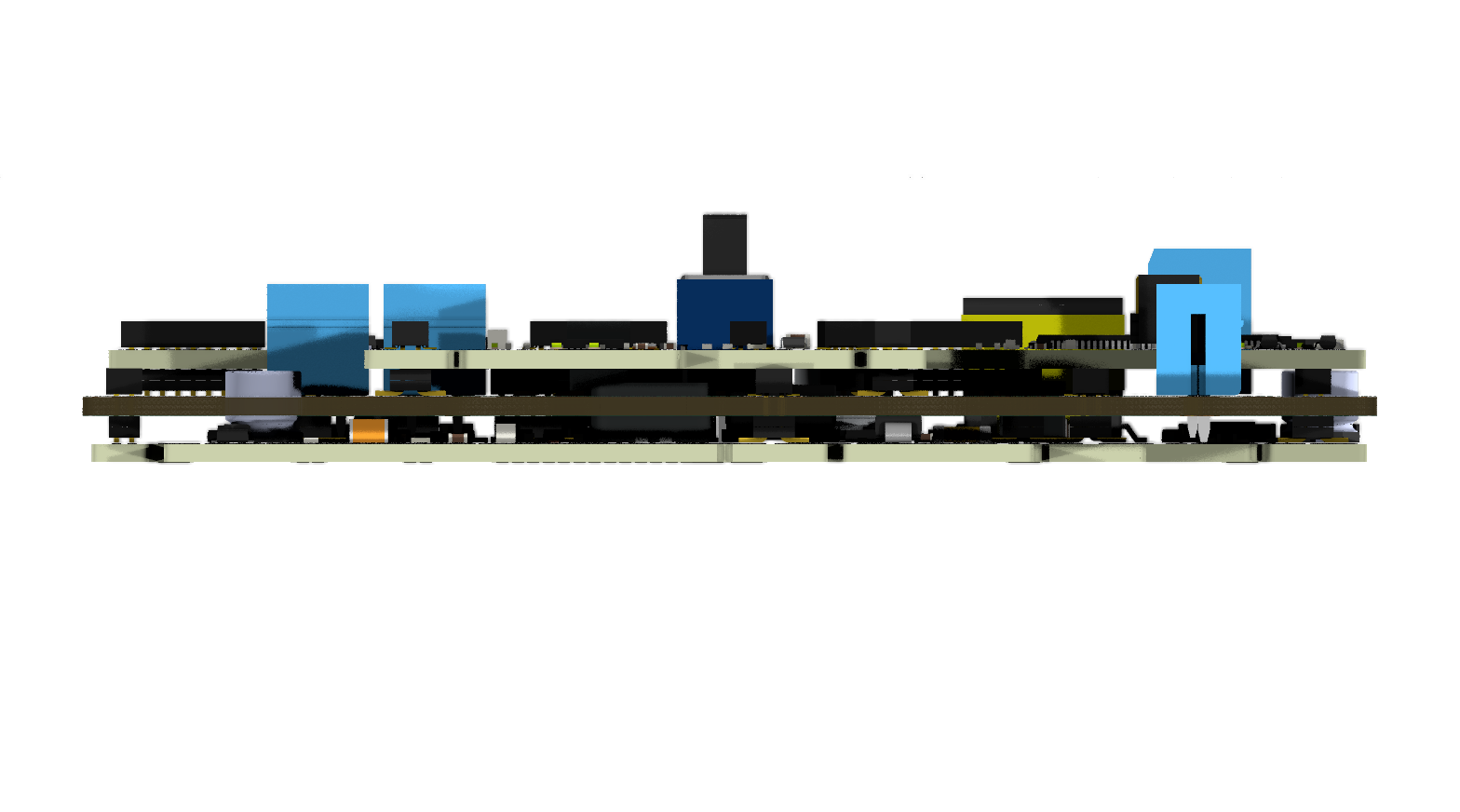 Right View of the PCB
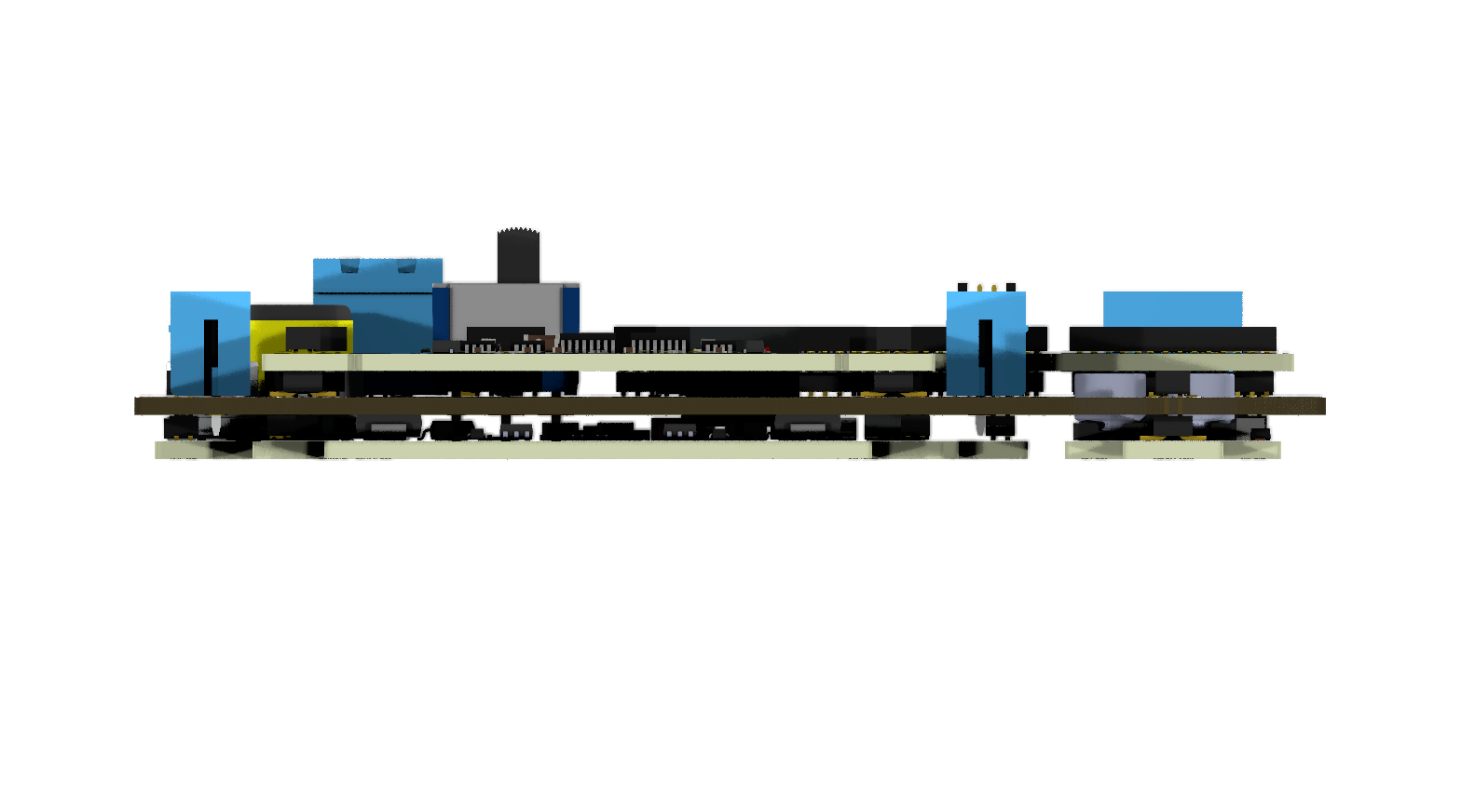 Front View of the PCB
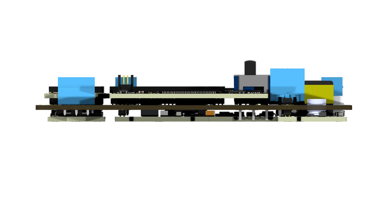 Back View of the PCB
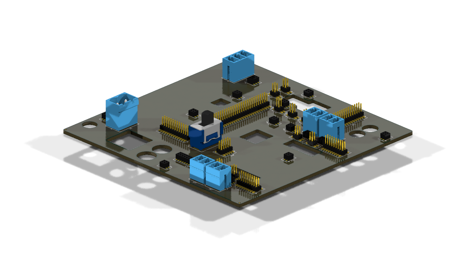 Side Exploded View 1
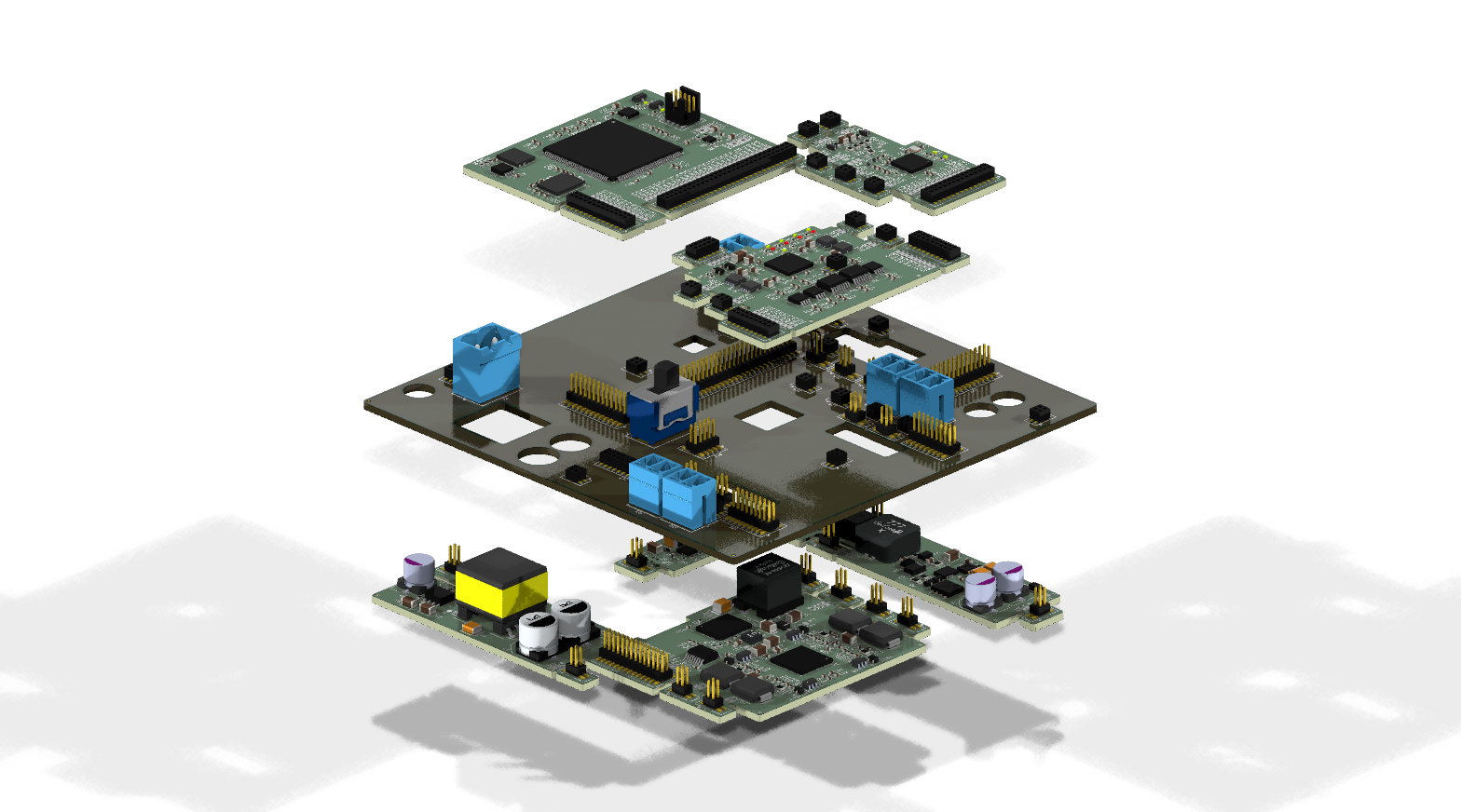 Side Exploded View 2
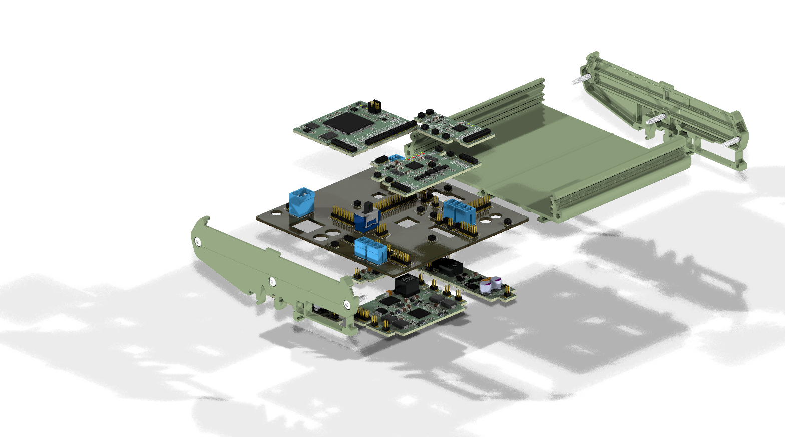 Side Exploded View 3
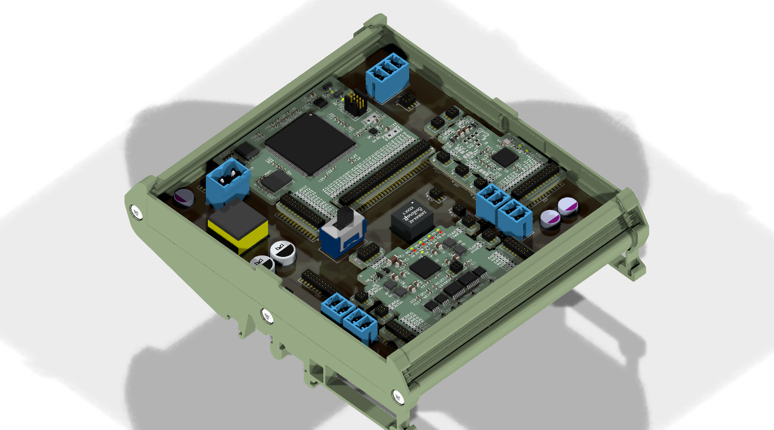 Side View with Enclosure
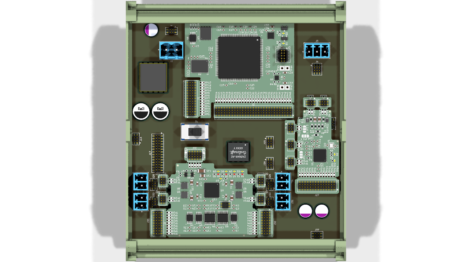 Top View with Enclosure
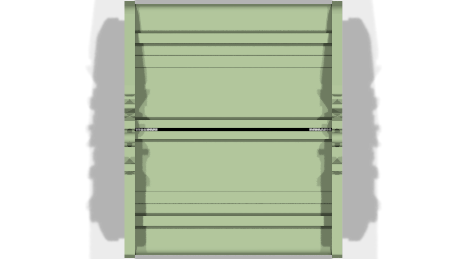 Bottom View with Enclosure
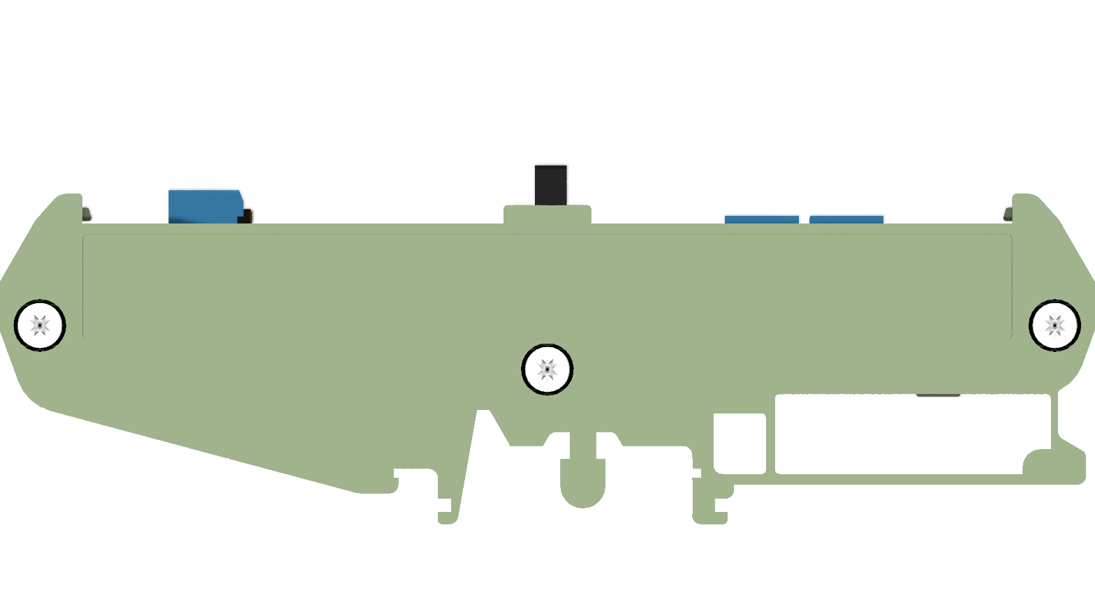 Left View with Enclosure
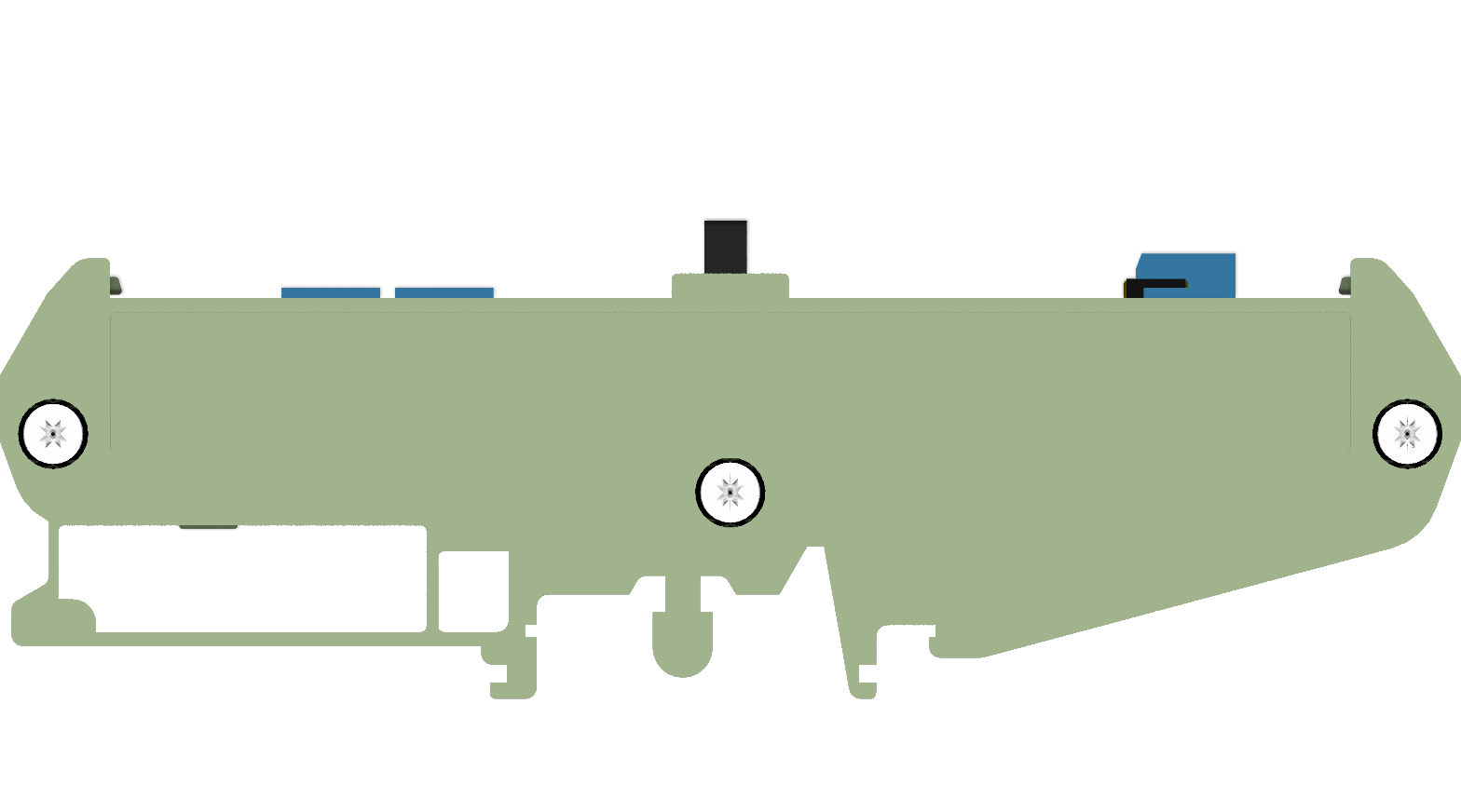 Right View with Enclosure
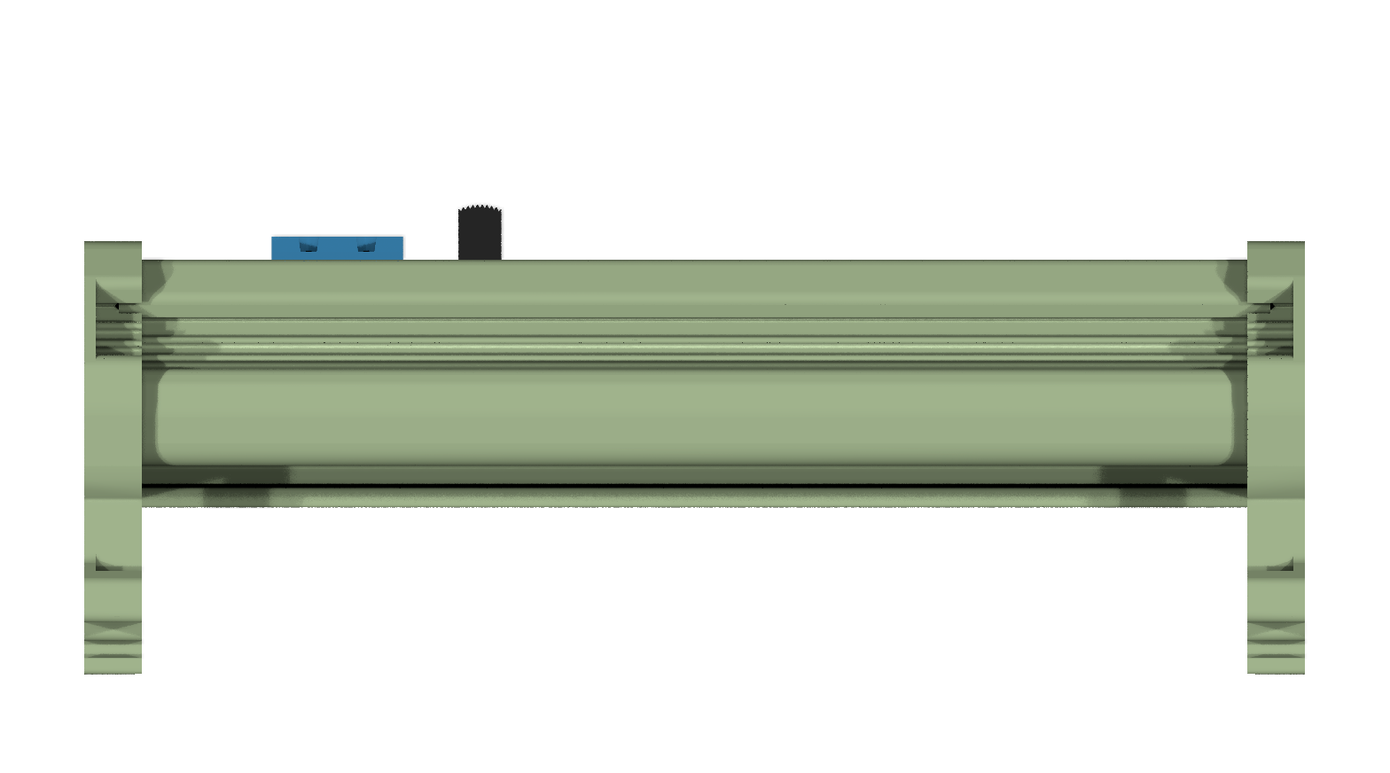 Front View with Enclosure
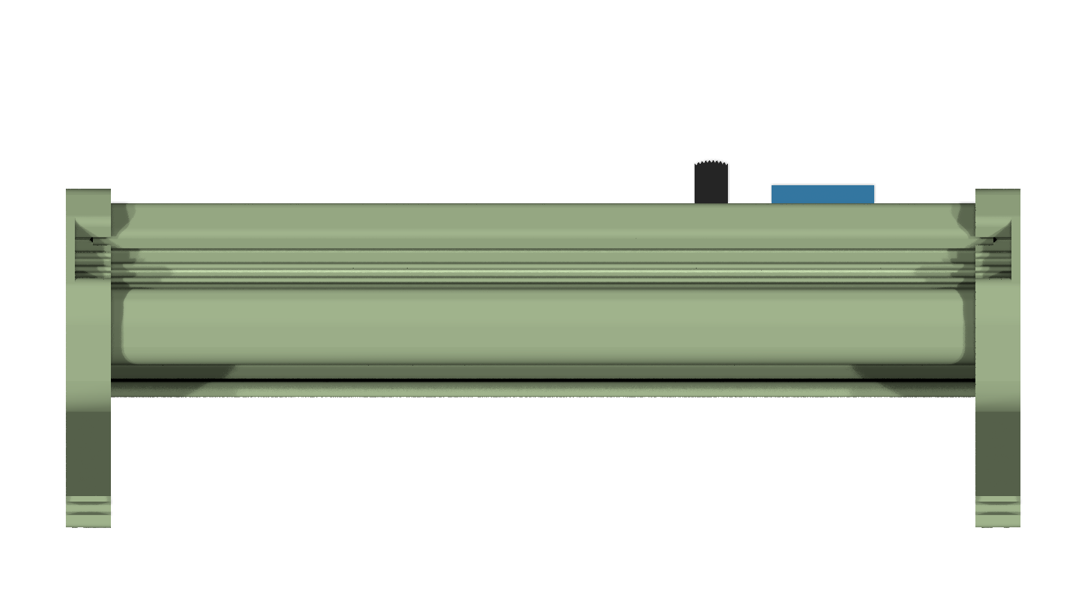 Back View with Enclosure
This project is licensed under the MIT License - see the LICENSE file for details.
| Qty | Value | Footprint | References |
|---|---|---|---|
| 14 | CLP-102-02-G-D-BE | connector_footprints:CLP-102-02-G-D-BE | J1, J5, J6, J11, J12, J14, J15, J20, J25, J26, J32, J33, J34, J37 |
| 9 | FW-02-03-G-D-085-155 | connector_footprints:FW-02-03-G-D-085-155 | J8, J9, J13, J16, J19, J21, J22, J28, J29 |
| 4 | TBP02R2-381-02BE | connector_footprints:TBP02R2-381-02BE | J23, J24, J30, J31 |
| 3 | Fiducial | no_components_footprints:Fiducial_0.5mm_Mask1mm | FID1, FID2, FID3 |
| 2 | FW-09-03-G-D-085-155 | connector_footprints:FW-09-03-G-D-085-155 | J35, J36 |
| 1 | 8SS1012-Z | slide_switches_footprints:8SS1012-Z | S1 |
| 1 | CLP-103-02-G-D-BE | connector_footprints:CLP-103-02-G-D-BE | J4 |
| 1 | CLP-114-02-G-D-BE | connector_footprints:CLP-114-02-G-D-BE | J17 |
| 1 | FW-05-03-G-D-085-155 | connector_footprints:FW-05-03-G-D-085-155 | J18 |
| 1 | FW-13-03-G-D-085-155 | connector_footprints:FW-13-03-G-D-085-155 | J7 |
| 1 | FW-14-03-G-D-085-155 | connector_footprints:FW-14-03-G-D-085-155 | J27 |
| 1 | FW-29-03-G-D-085-155 | connector_footprints:FW-29-03-G-D-085-155 | J10 |
| 1 | TBP02R2-381-03BE | connector_footprints:TBP02R2-381-03BE | J3 |
| 1 | TBP04R2-500-02BE | connector_footprints:TBP04R2-500-02BE | J2 |
| 1 | ~ | modules_footprints:minimal_adin1110 | MOD4 |
| 1 | ~ | modules_footprints:minimal_max17761 | MOD2 |
| 1 | ~ | modules_footprints:minimal_ad74413r | MOD6 |
| 1 | ~ | modules_footprints:minimal_ltc9111 | MOD5 |
| 1 | ~ | modules_footprints:minimal_lt8304 | MOD3 |
| 1 | ~ | mechanical_parts:2959683 | M3 |
| 1 | ~ | mechanical_parts:2959696 | M1 |
| 1 | ~ | modules_footprints:minimal_max14906 | MOD7 |
| 1 | ~ | mechanical_parts:2907525 | M2 |
| 1 | ~ | modules_footprints:minimal_max32650 | MOD1 |

MARS-UVA/Jetson_Extension_Board
KiCad design files for the Jetson Extension Board

DPIclimate/ag-node
Automatic multi-weigh-station for measuring the live-weight of sheep in remote locations.

HarveyBates/Open-JIP
An open-source Arduino based chlorophyll fluorometer for quantifying photosynthesis in photosynthetic organisms.

hackclub/OnBoard
💡 Join 1,000 teenagers and make your first PCB with a $100 grant!


murexrobotics/electrical
Highly integrated electronics design and printed circuit boards (PCBs) for the MATE ROV Competition. Attempt the impossible.
It measures 105 × 107 mm and has 4 copper layers, 1.6 mm thick.
51 parts, built around the CLP-102-02-G-D-BE, TBP02R2-381-02BE, 8SS1012-Z and CLP-103-02-G-D-BE. The full list of its parts is on this page, with links to each part's symbol and footprint where PCBKit's library has them.
From the ionutms/Modular_Software_Configurable_IO_PLC repository on GitHub, at the commit this page was made from: the board is modular_software_configurable_io_plc/modular_software_configurable_io_plc.kicad_pcb and its schematic modular_software_configurable_io_plc/MCU.kicad_sch. PCBKit opens the board in the browser, with nothing to install.
Its repository publishes it under the MIT licence: you may reuse it on that licence's terms (keep the author's notice, and for a copyleft licence share your changes alike).