
2 layers60 × 30 mm
Controller
google/mozc-devices
Circuit diagrams and firmware source code for Gboard DIY keyboards
11 parts3kApache-2.0

 imguxuuuu/Battery-Protection-PCB1
Manufacturing-ready Li-Ion Battery Protection PCB designed using KiCad 9 with complete documentation, Gerber files, simulations, and manufacturing package.
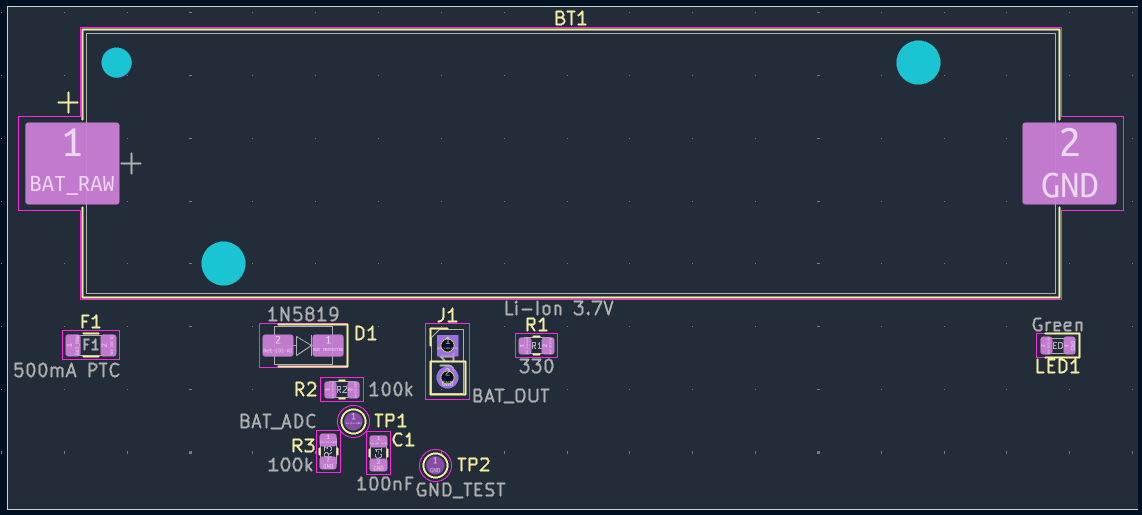
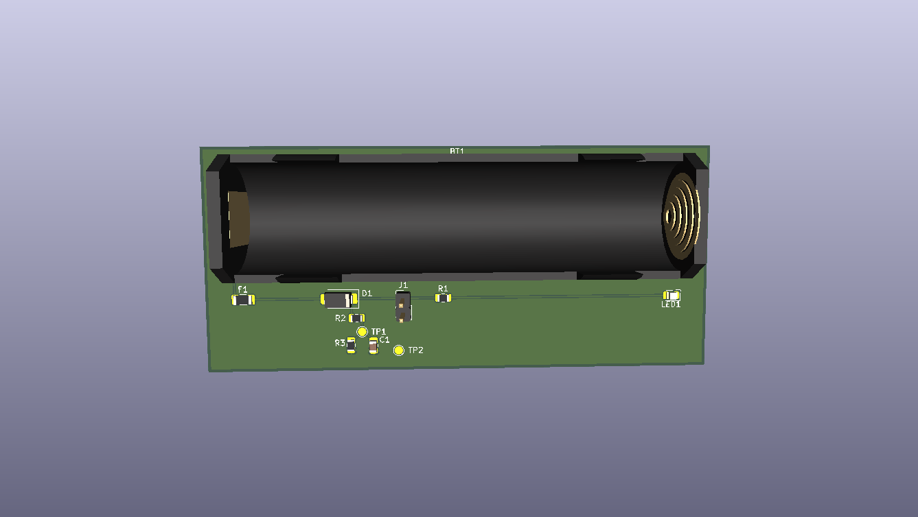
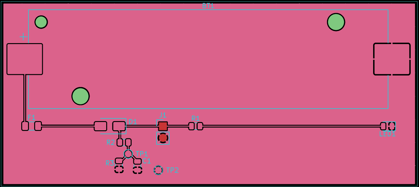
LiIon Battery Protection is an open-source printed circuit board by imguxuuuu, from the imguxuuuu/Battery-Protection-PCB repository on GitHub, published under the MIT licence. It is a 2-layer board of 90 × 40 mm with 11 parts on 6 nets, routed with 23 tracks and 0 vias.
Its parts include 3 resistors, 2 diodes, 1 capacitor, 1 connector and 1 fuse. It belongs with the power boards of this library.




A compact single-cell (3.7 V) Li-Ion battery protection and voltage monitoring PCB designed using KiCad 9.
This project demonstrates the complete PCB design workflow, including schematic capture, PCB layout, routing, copper pour, design rule verification, Gerber generation, and manufacturing documentation.
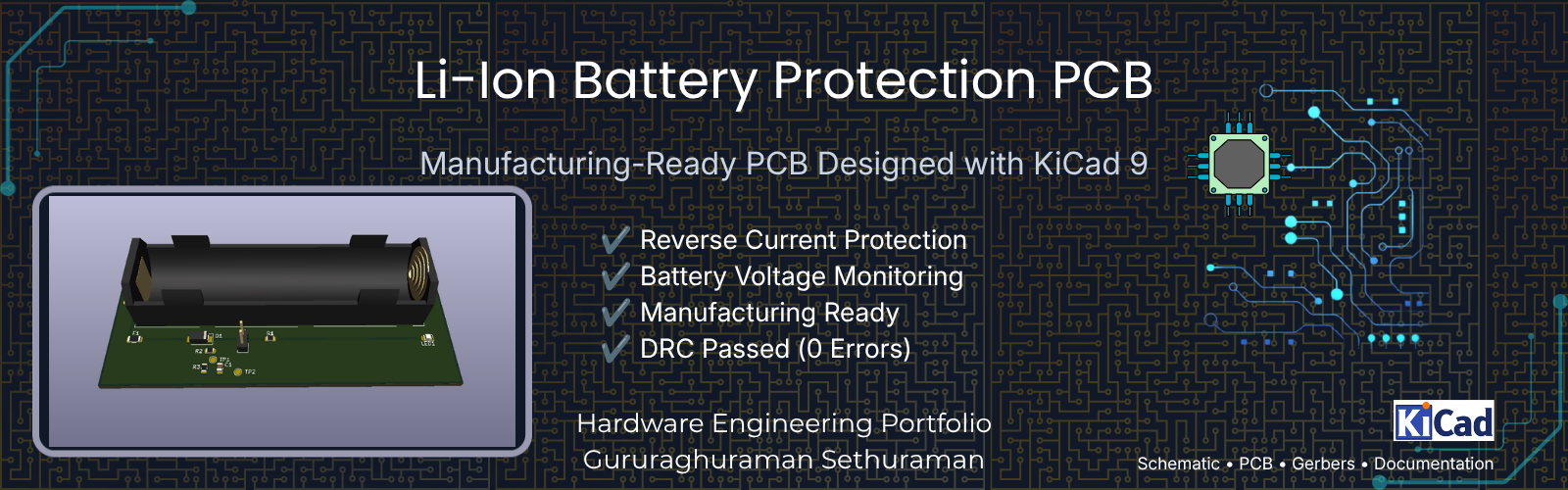
This PCB provides a simple yet reliable protection and monitoring solution for a single-cell Li-Ion battery.
The design includes:
The project was developed to demonstrate practical PCB design skills and follows good engineering documentation practices suitable for a hardware portfolio.
| Parameter | Value |
|---|---|
| Board Size | 90 mm × 40 mm |
| Layers | 2 |
| Copper Weight | 1 oz |
| Input Voltage | 3.0–4.2 V DC |
| Nominal Voltage | 3.7 V Li-Ion |
| Design Software | KiCad 9 |
| DRC Status | Passed (0 Errors) |
The battery output first passes through a 500 mA resettable Polyfuse, providing overcurrent protection.
The protected voltage is then routed through a 1N5819 Schottky diode, preventing reverse current flow.
The output powers:
Battery voltage is measured using a 100 kΩ / 100 kΩ resistor divider followed by a 100 nF RC filter, providing a stable analog voltage for a microcontroller ADC.
Battery
   │
   ▼
PTC Fuse
   │
   ▼
Schottky Diode
   │
   ▼
BAT_OUT
 ├──► LED Indicator
 └──► ADC Voltage Divider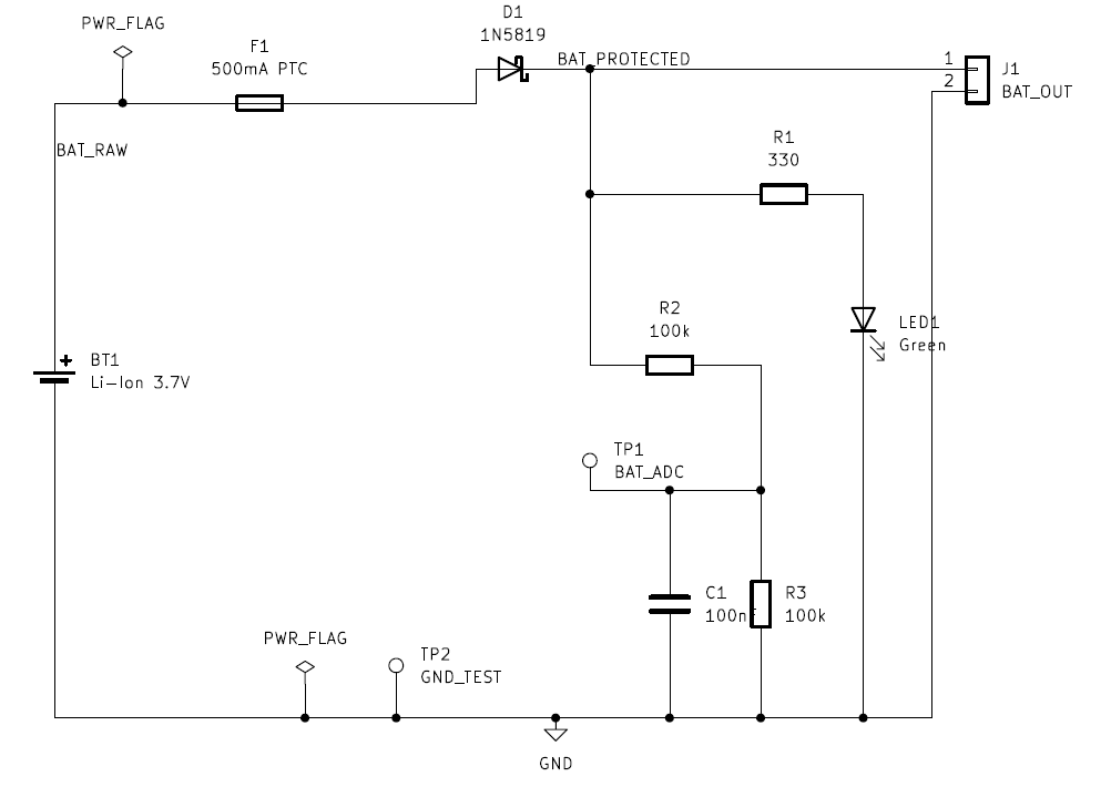
docs/
gerbers/
images/
pcb/
references/
releases/
simulation/See BOM.csv
This project is licensed under the MIT License.
See the LICENSE file for details.
Designed using KiCad 9 as part of a hardware engineering portfolio project demonstrating PCB design, documentation, and manufacturing preparation.
| Qty | Value | Footprint | References |
|---|---|---|---|
| 2 | 100k | Resistor_SMD:R_0805_2012Metric | R2, R3 |
| 1 | 100nF | Capacitor_SMD:C_0805_2012Metric | C1 |
| 1 | 1N5819 | Diode_SMD:D_SMA | D1 |
| 1 | 330 | Resistor_SMD:R_0805_2012Metric | R1 |
| 1 | 500mA PTC | Fuse:Fuse_1206_3216Metric | F1 |
| 1 | BAT_ADC | TestPoint:TestPoint_Pad_D1.5mm | TP1 |
| 1 | BAT_OUT | Connector_PinHeader_2.54mm:PinHeader_1x02_P2.54mm_Vertical | J1 |
| 1 | GND_TEST | TestPoint:TestPoint_Pad_D1.5mm | TP2 |
| 1 | Green | LED_SMD:LED_0805_2012Metric | LED1 |
| 1 | Li-Ion 3.7V | Battery:BatteryHolder_Keystone_1042_1x18650 | BT1 |
google/mozc-devices
Circuit diagrams and firmware source code for Gboard DIY keyboards


FrameworkComputer/ExpansionCards
Reference designs and documentation to create Expansion Cards for the Framework Laptop

hoglet67/RGBtoHDMI
Bare-metal Raspberry Pi project that provides pixel-perfect sampling of Retro Computer RGB/YUV video and conversion to HDMI

hackclub/OnBoard
💡 Join 1,000 teenagers and make your first PCB with a $100 grant!


tardate/LittleArduinoProjects
a collection of "Little Electronic & Arduino Projects", most involving electronics or an Arduino in one way or another!

basilfx/TRADFRI-Hacking
Hacking IKEA TRÅDFRI products, such as light bulbs, window blinds and other accessories.
It measures 90 × 40 mm and has 2 copper layers, 1.6 mm thick.
11 parts. The full list of its parts is on this page, with links to each part's symbol and footprint where PCBKit's library has them.
From the imguxuuuu/Battery-Protection-PCB repository on GitHub, at the commit this page was made from: the board is pcb/LiIon_Battery_Protection/LiIon_Battery_Protection.kicad_pcb and its schematic pcb/LiIon_Battery_Protection/LiIon_Battery_Protection.kicad_sch. PCBKit opens the board in the browser, with nothing to install.
Its repository publishes it under the MIT licence: you may reuse it on that licence's terms (keep the author's notice, and for a copyleft licence share your changes alike).