2 layers89.1 × 65.1 mm

 imaginaryimpedance/Differential-Probe1
Device is based on AD8130 differential amplifier and THS3491 amplifier on output stage.
Differential Probe is an open-source printed circuit board by imaginaryimpedance, from the imaginaryimpedance/Differential-Probe repository on GitHub. It is a 4-layer board of 100 × 50 mm with 197 parts on 101 nets, routed with 683 tracks and 213 vias.
It is built around the OPA187ID, AD8130ARM and TPS65130RGE, with the LM339, 1N4148W and EE2-5NU among its other parts. Its parts include 69 resistors, 66 capacitors, 13 diodes, 6 ICs and 4 connectors. It belongs with the sensors and measurement boards of this library.


Purpose of this project was to design low cost differential probe with attenuations of x10 and x100 to measure voltages up to 1kV with bandwidth of atleast 10MHz. Input range for x100 attenuation is 1kV, for x10 it is 100V. Simulated bandwidth of this probe is estimated at 100MHz. Testing only proved bandwidth of 25MHz as it is limited by Analog Discovery 2 network analyzer max frequency. Cost per 1 unit is below 100 euro. Power is delivered by USB-C.
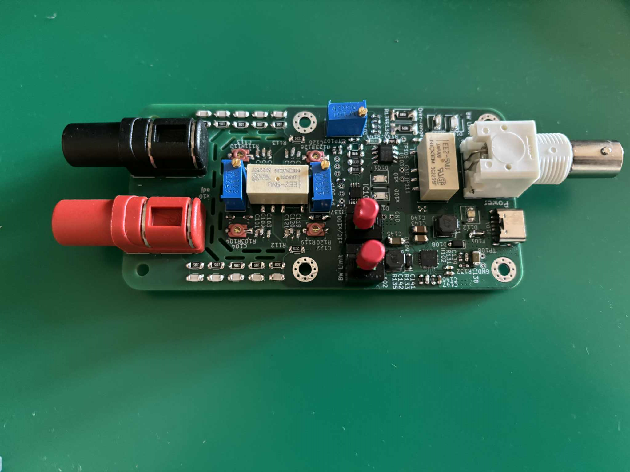
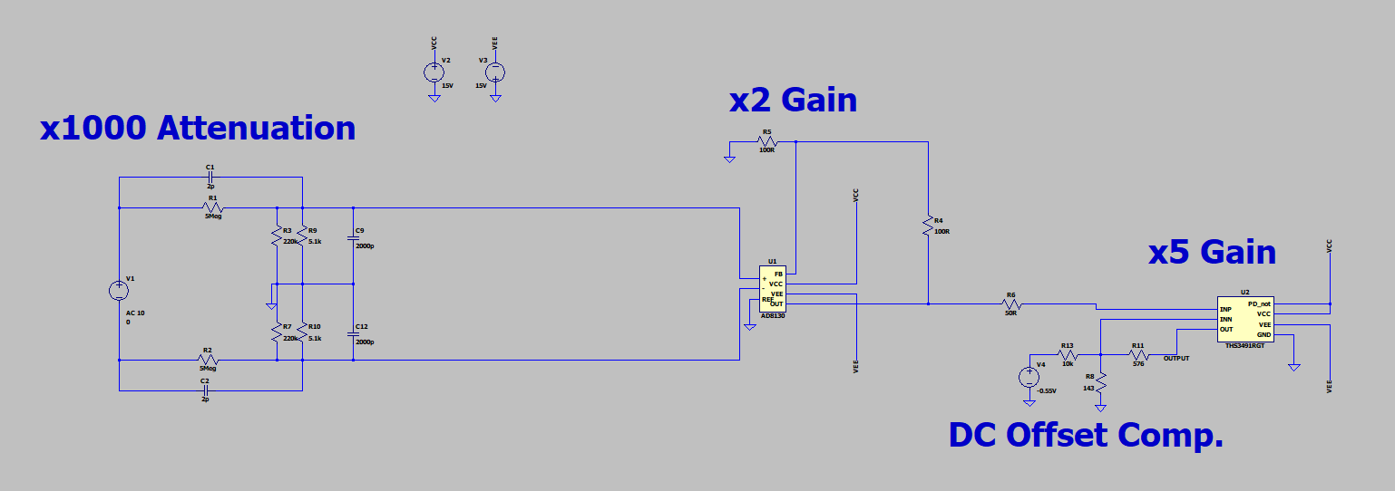
Device is based on AD8130 differential amplifier and THS3491 amplifier on output stage.
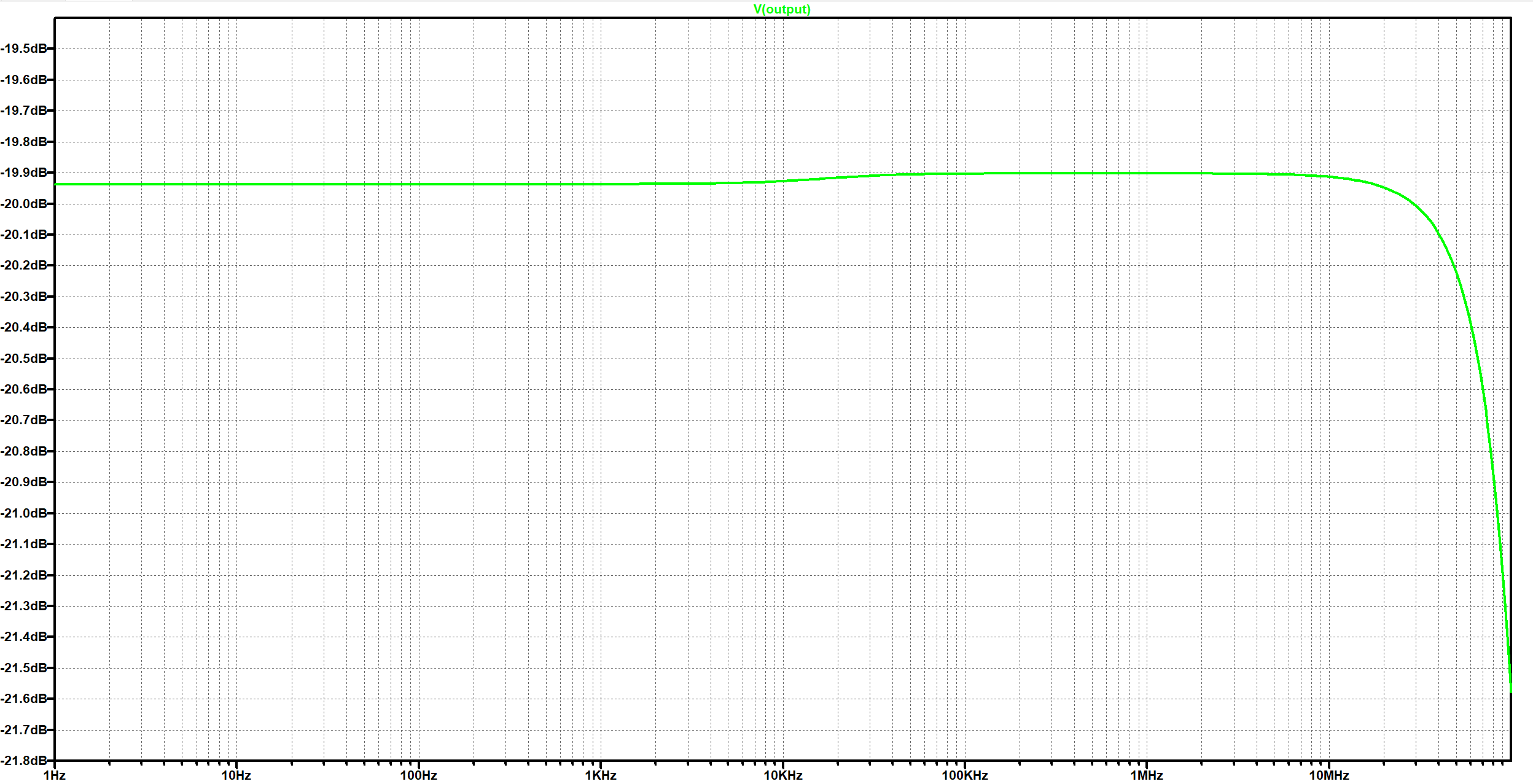
Bandwidth according to simulation is above 100MHz:
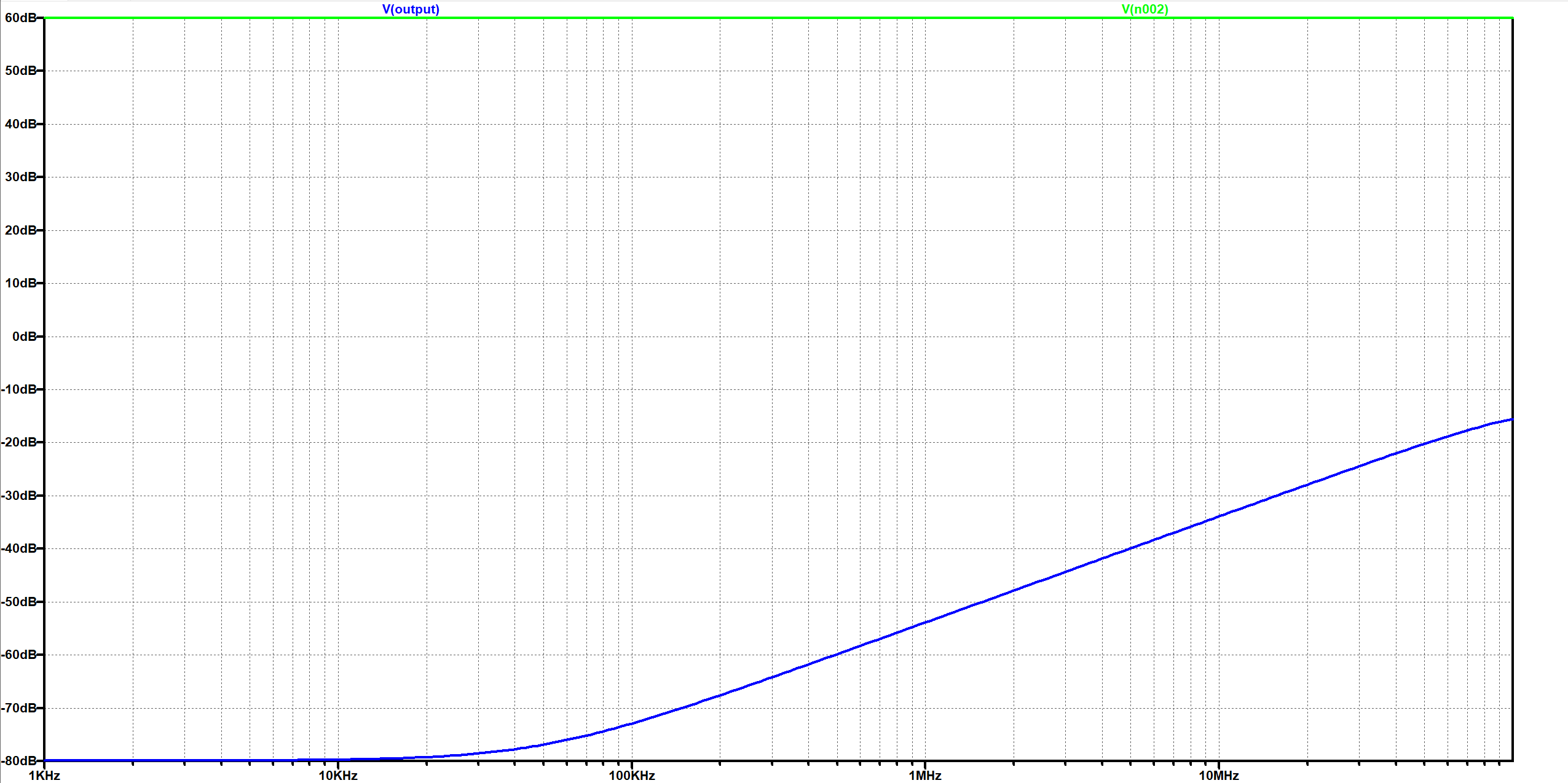
CMRR is 65dB in worst case, 140dB for DC and frequencies below 20kHz:
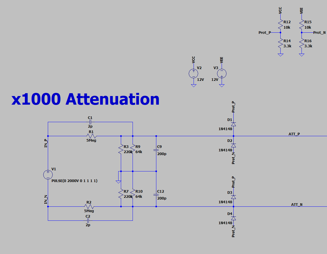
Gain of the amplifying stage is constant at 10. Attenuation is switched between 1000 and 100 by relay.
Input protection is done by 1N4148 diodes as they have really low parasitic capacitance.
As maximum differential input voltage for AD8130 is 8.4V
they are connected to resistor dividers ensuring 8V is not exceeded in case of 5 times of maximum voltage input
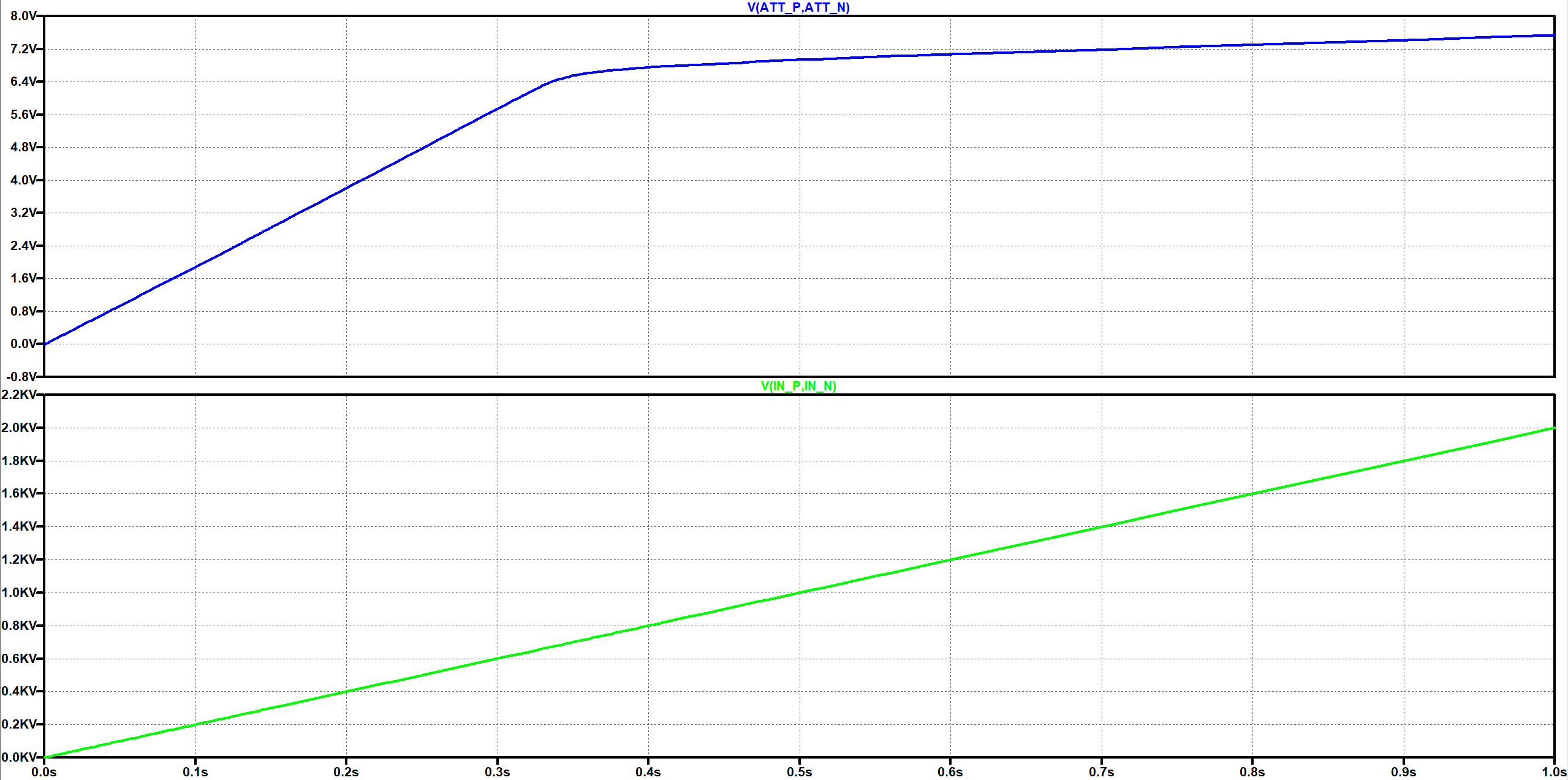
Simulated plot for x10 attenuation with 2kV input:
DC offset can be adjusted by introducing small DC voltage to non inverting input of output amplifier.
Device is equipped with switchable 5MHz output low pass filter
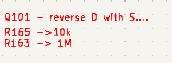
Version v1.0 has wrong pinout for U106, Q101, and SW101. To rework U106 and SW101 some traces must be cut. All design important notes for fixes in reference to original design are written in red in schematics file.
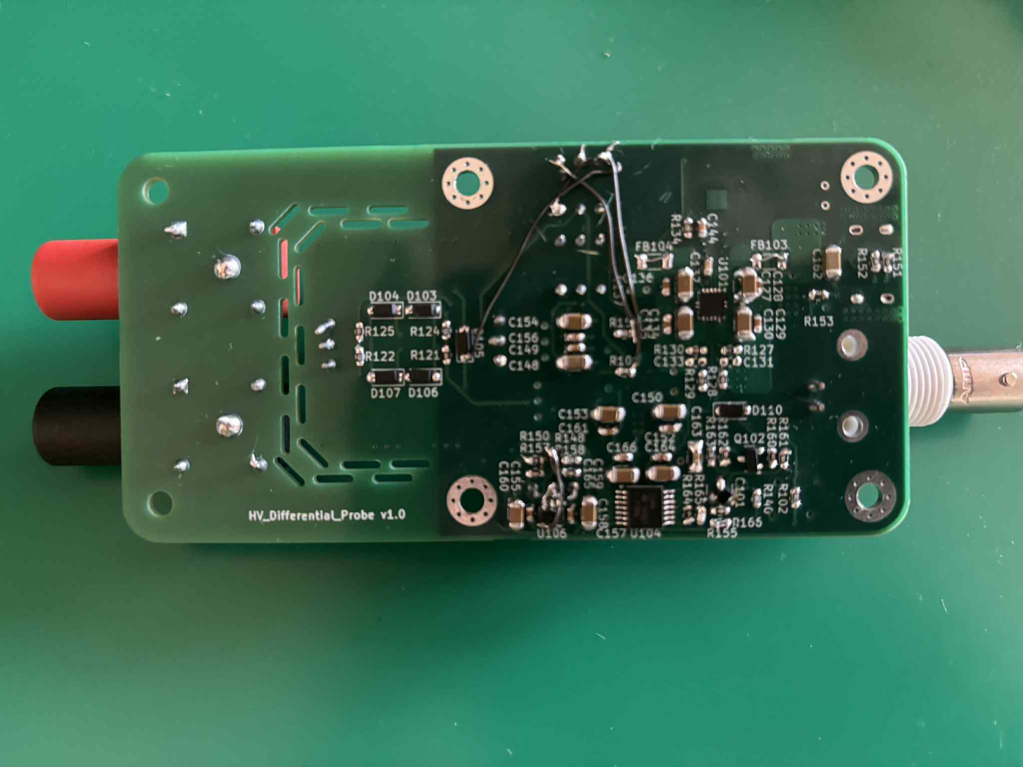
Voltages on Test points TP110 and TP111 should provide really clean and stable 11.9V voltage.
To achieve even attenuation for positive and negative input, remove resistors R137 and R138, force DC voltage floating from probe power supply ground and adjust potentiometers RV101 for x10 and RV102 for x100 so voltages between GND and test points TP103 and TP104 are equal.
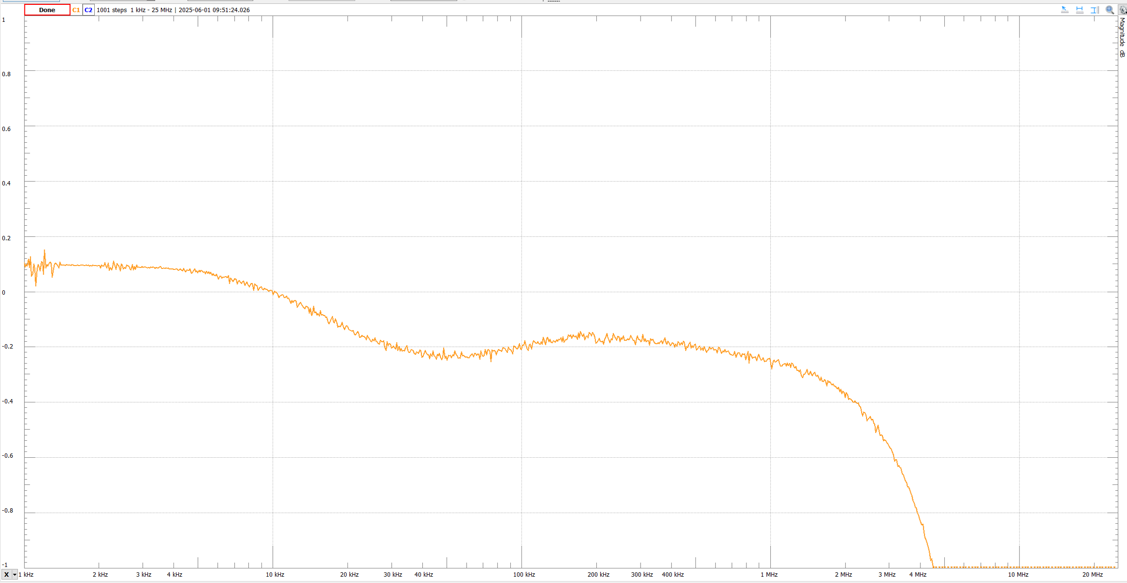
Using device with Bode Plot funcionality, for example Analog Discovery 2, connect generator to positive input and coaxial shield to negative, and adjust variable capacitors on positive side of attenuator for flat frequency response:
Example of unadjusted probe
After adjusting:
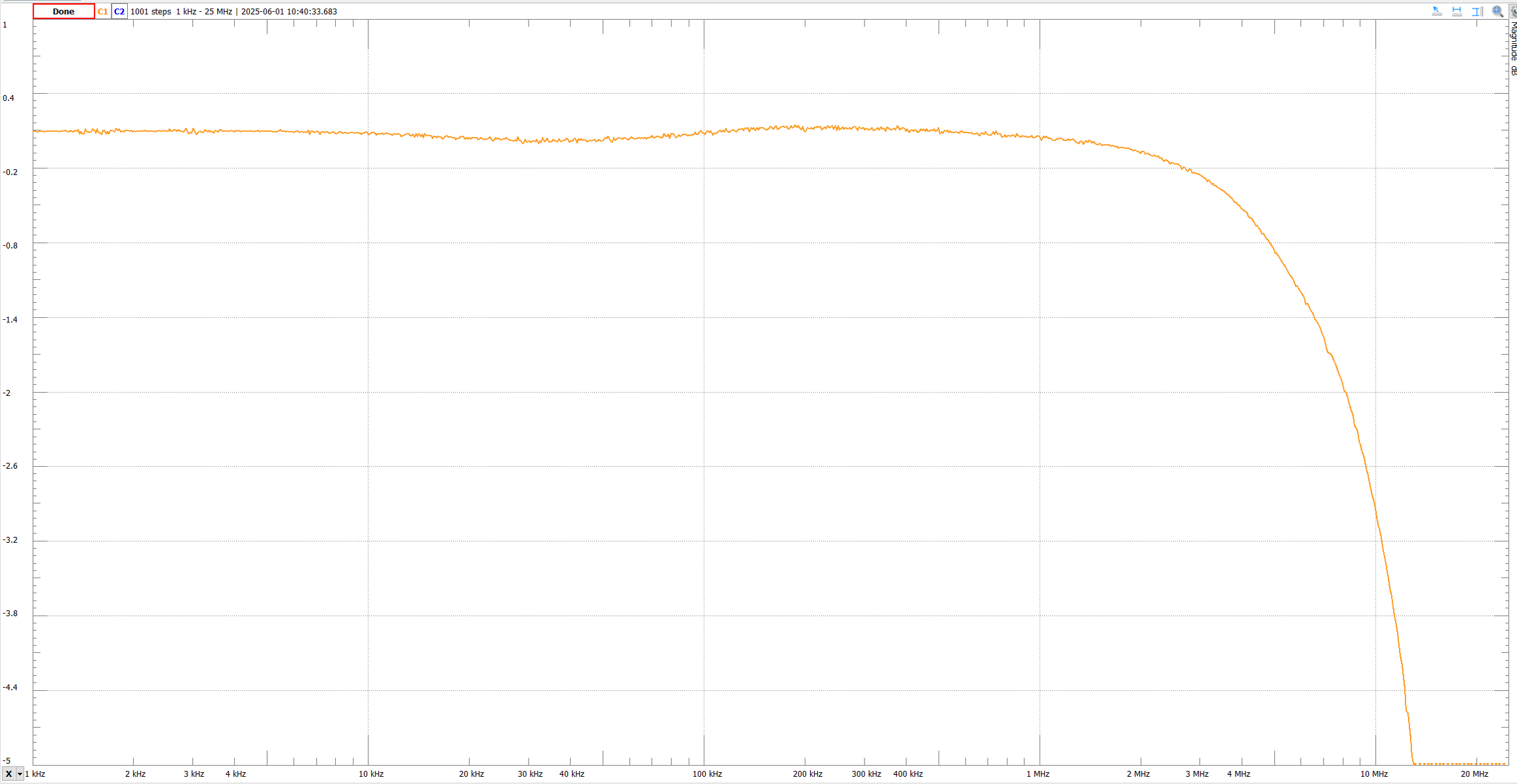
Repeat with switched positive and negative input for both x10 and x100.
Note: AD2 max bandwidth is 25MHz:
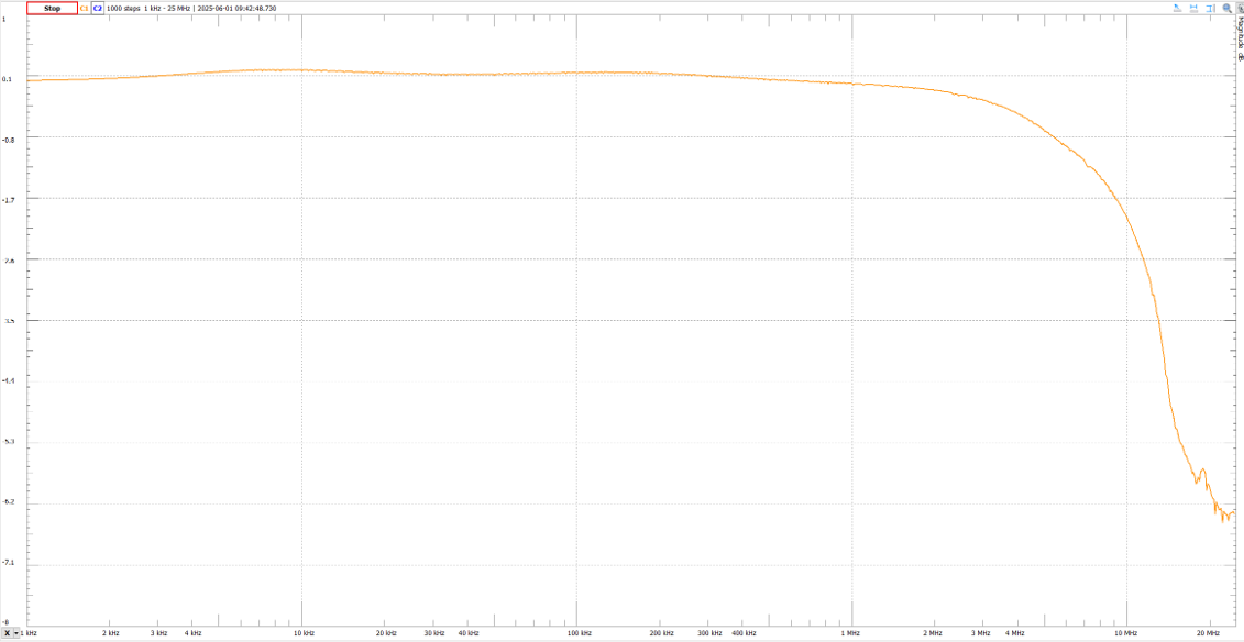
On this step, 5MHz output filter can also be checked and adjusted.
Short positive and negative inputs and connect DMM to the output. Adjust potentiometer RV103 to achieve near-zero offset.
| Qty | Value | Footprint | References |
|---|---|---|---|
| 15 | 10k | Resistor_SMD:R_0603_1608Metric | R121, R125, R128, R129, R151, R152, R153, R155, R157, R158, R160, R168, R169, R170, R171 |
| 14 | TestPoint | TestPoint:TestPoint_THTPad_D1.0mm_Drill0.5mm | GND, GND, GND, GND, GND, TP103, TP104, TP105, TP106, TP107, TP108, TP109, TP110, TP111 |
| 13 | 100n | Capacitor_SMD:C_0603_1608Metric | C127, C130, C135, C136, C144, C149, C152, C155, C156, C158, C161, C164, C166 |
| 10 | 10p | Capacitor_SMD:C_1206_3216Metric | C105, C106, C107, C108, C109, C114, C115, C116, C117, C118 |
| 10 | 10u | Capacitor_SMD:C_1206_3216Metric | C128, C129, C134, C137, C148, C154, C157, C159, C160, C165 |
| 10 | 1M | Resistor_SMD:R_1206_3216Metric | R105, R106, R107, R108, R109, R114, R115, R116, R117, R118 |
| 6 | 100k | Resistor_SMD:R_0603_1608Metric | R130, R133, R142, R148, R150, R164 |
| 5 | 1k | Resistor_SMD:R_0603_1608Metric | R101, R102, R140, R154, R165 |
| 5 | VLP600R | SamacSys_Parts:VLP600R | H**, H**, H**, H**, H** |
| 4 | 0R | Resistor_SMD:R_0603_1608Metric | R120, R123, R137, R138 |
| 4 | 10n | Capacitor_SMD:C_0603_1608Metric | C131, C132, C133, C146 |
| 4 | 1N4148W | Diode_SMD:D_SOD-123 | D103, D104, D106, D107 |
| 4 | 8-30p | Capacitor_SMD:C_Trimmer_Murata_TZB4-A | C104, C113, C122, C126 |
| 3 | 10R | Resistor_SMD:R_0603_1608Metric | R161, R162, R166 |
| 3 | 22u | Capacitor_SMD:C_1206_3216Metric | C138, C145, C162 |
| 3 | BLED | Diode_SMD:D_1206_3216Metric | D101, D102, D113 |
| 2 | 1.5k, 0.1% | Resistor_SMD:R_0603_1608Metric | R104, R110 |
| 2 | 1.5n, 1% | Capacitor_SMD:C_0603_1608Metric | C119, C123 |
| 2 | 100R | Potentiometer_THT:Potentiometer_Bourns_3296W_Vertical | RV102, RV103 |
| 2 | 100R, 0.1% | Resistor_SMD:R_1206_3216Metric | R141, R145 |
| 2 | 10p, 1% | Capacitor_SMD:C_0603_1608Metric | C103, C112 |
| 2 | 120p, 1% | Capacitor_SMD:C_0603_1608Metric | C101, C110 |
| 2 | 2.2k | Resistor_SMD:R_0603_1608Metric | R167, R172 |
| 2 | 20pF, 1%/50pF 1% | Capacitor_SMD:C_0603_1608Metric | C121, C125 |
| 2 | 220k, 0.1% | Capacitor_SMD:C_1206_3216Metric | R112, R113 |
| 2 | 3.3k | Resistor_SMD:R_0603_1608Metric | R122, R124 |
| 2 | 4.7u | Capacitor_SMD:C_1206_3216Metric | C140, C143 |
| 2 | 4.7uH | Inductor_SMD:L_APV_ANR5040 | L101, L102 |
| 2 | 420pF, 1% | Capacitor_SMD:C_0603_1608Metric | C120, C124 |
| 2 | 49.9R | Resistor_SMD:R_1206_3216Metric | R156, R159 |
| 2 | 49.9R | Resistor_SMD:R_2512_6332Metric | R136, R139 |
| 2 | 5.1k, 0.1% | Resistor_SMD:R_0603_1608Metric | R119, R126 |
| 2 | 50p, 1% | Capacitor_SMD:C_0603_1608Metric | C102, C111 |
| 2 | 6.8p | Capacitor_SMD:C_0603_1608Metric | C139, C142 |
| 2 | 6.8u | Capacitor_SMD:C_1206_3216Metric | C150, C153 |
| 2 | 62k, 0.1% | Resistor_SMD:R_0603_1608Metric | R103, R111 |
| 2 | Conn_01x01_Socket | SamacSys_Parts:SWEB8094AuRT | J101, J103 |
| 2 | D_Small | Diode_SMD:D_SOD-123 | D105, D110 |
| 2 | EE2-5NU | Relay_SMD:Relay_DPDT_Kemet_EE2_NU | K101, K102 |
| 2 | FerriteBead_Small | Inductor_SMD:L_1206_3216Metric | FB103, FB104 |
| 2 | TL2202EEYA | SamacSys_Parts:MHPS2285 | SW101, SW102 |
| 1 | 1.3M | Resistor_SMD:R_0603_1608Metric | R135 |
| 1 | 100R | Resistor_SMD:R_0603_1608Metric | R134 |
| 1 | 143R, 0.1% | Resistor_SMD:R_1206_3216Metric | R144 |
| 1 | 1M | Resistor_SMD:R_0603_1608Metric | R131 |
| 1 | 1k | Potentiometer_THT:Potentiometer_Bourns_3296W_Vertical | RV101 |
| 1 | 220n | Capacitor_SMD:C_0603_1608Metric | C141 |
| 1 | 3.3M | Resistor_SMD:R_0603_1608Metric | R163 |
| 1 | 300mA | Fuse:Fuse_1206_3216Metric | F101 |
| 1 | 300p | Capacitor_SMD:C_0603_1608Metric | C151 |
| 1 | 330n | Capacitor_SMD:C_1206_3216Metric | C163 |
| 1 | 4.7n | Capacitor_SMD:C_0603_1608Metric | C147 |
| 1 | 576R, 0.1% | Resistor_SMD:R_1206_3216Metric | R143 |
| 1 | 88k | Resistor_SMD:R_0603_1608Metric | R132 |
| 1 | 90.9k | Resistor_SMD:R_0603_1608Metric | R127 |
| 1 | AD8130ARM | SamacSys_Parts:SOP65P490X110-8N | IC101 |
| 1 | AO3400A | Package_TO_SOT_SMD:SOT-23 | Q102 |
| 1 | AO3401A | Package_TO_SOT_SMD:SOT-23 | Q101 |
| 1 | Conn_Coaxial | SamacSys_Parts:2269901 | J102 |
| 1 | D_Schottky_Small | Diode_SMD:D_SOD-123 | D108 |
| 1 | GLED | Diode_SMD:D_1206_3216Metric | D112 |
| 1 | LM339 | Package_SO:TSSOP-14_4.4x5mm_P0.65mm | U104 |
| 1 | OPA187I | Package_TO_SOT_SMD:SOT-23-5 | U106 |
| 1 | RLED | Diode_SMD:D_1206_3216Metric | D111 |
| 1 | THS3491xDDA | Package_SO:Texas_R-PDSO-G8_EP2.95x4.9mm_Mask2.4x3.1mm | U103 |
| 1 | TPS65130RGE | Package_DFN_QFN:VQFN-24-1EP_4x4mm_P0.5mm_EP2.45x2.45mm_ThermalVias | U102 |
| 1 | TPS7A39 | Package_SON:Texas_S-PVSON-N10_ThermalVias | U101 |
| 1 | USB_C_Receptacle_PowerOnly_6P | Connector_USB:USB_C_Receptacle_GCT_USB4125-xx-x_6P_TopMnt_Horizontal | J104 |
| 1 | xxx | Diode_SMD:D_SOD-123 | D109 |
The 191 most common of 197 parts.

PavlinaMos/soil-moisture-sensor-thesis
The current status of my thesis including firmware, PCB design, writing

Alacrity-Education/DemoBoards
Small boards for educational and demo purposes


precision-sustainable-ag/PlantMap3D-Hardware
The system management board handles all power distribution in the multi-camera system and a few other auxiliary functions. The PCB is designed using KiCad.

gabriele-moretto/dinospand
Agricultural PCB project design and firmware developing.
It measures 100 × 50 mm and has 4 copper layers, 1.61 mm thick.
197 parts, built around the OPA187ID, AD8130ARM, TPS65130RGE and LM339. The full list of its parts is on this page, with links to each part's symbol and footprint where PCBKit's library has them.
From the imaginaryimpedance/Differential-Probe repository on GitHub, at the commit this page was made from: the board is Differential_Probe_PCB/Differential_Probe.kicad_pcb and its schematic Differential_Probe_PCB/Amplifier.kicad_sch. PCBKit opens the board in the browser, with nothing to install.
Its repository states no licence, so its author keeps all rights: ask imaginaryimpedance before reusing the design.