


2 layers327.9 × 139 mm
Coco2
baldengineer/bit-preserve
Project for capturing vintage, classic, aka old computer schematics in KiCad.
147 parts446

 ikatkov/inductor-tester2
Power) Inductor saturation current tester
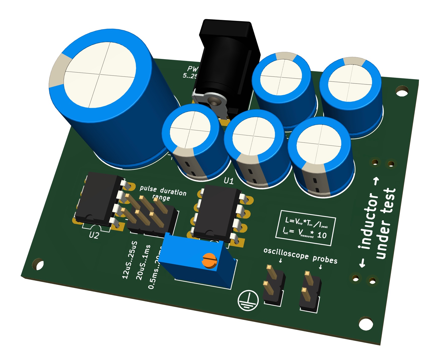
Inductor tester is an open-source printed circuit board by ikatkov, from the ikatkov/inductor-tester repository on GitHub. It is a 4-layer board of 62.5 × 46.2 mm with 36 parts on 17 nets, routed with 156 tracks and 4 vias.
It is built around the NE555P and SS34. Its parts include 14 capacitors, 6 connectors, 4 resistors, 2 ICs and 2 diodes.
~60A max current. Power supply 5-25V. Based on http://elm-chan.org/works/lchk/report.html
You will need an oscilloscope to take measurements.
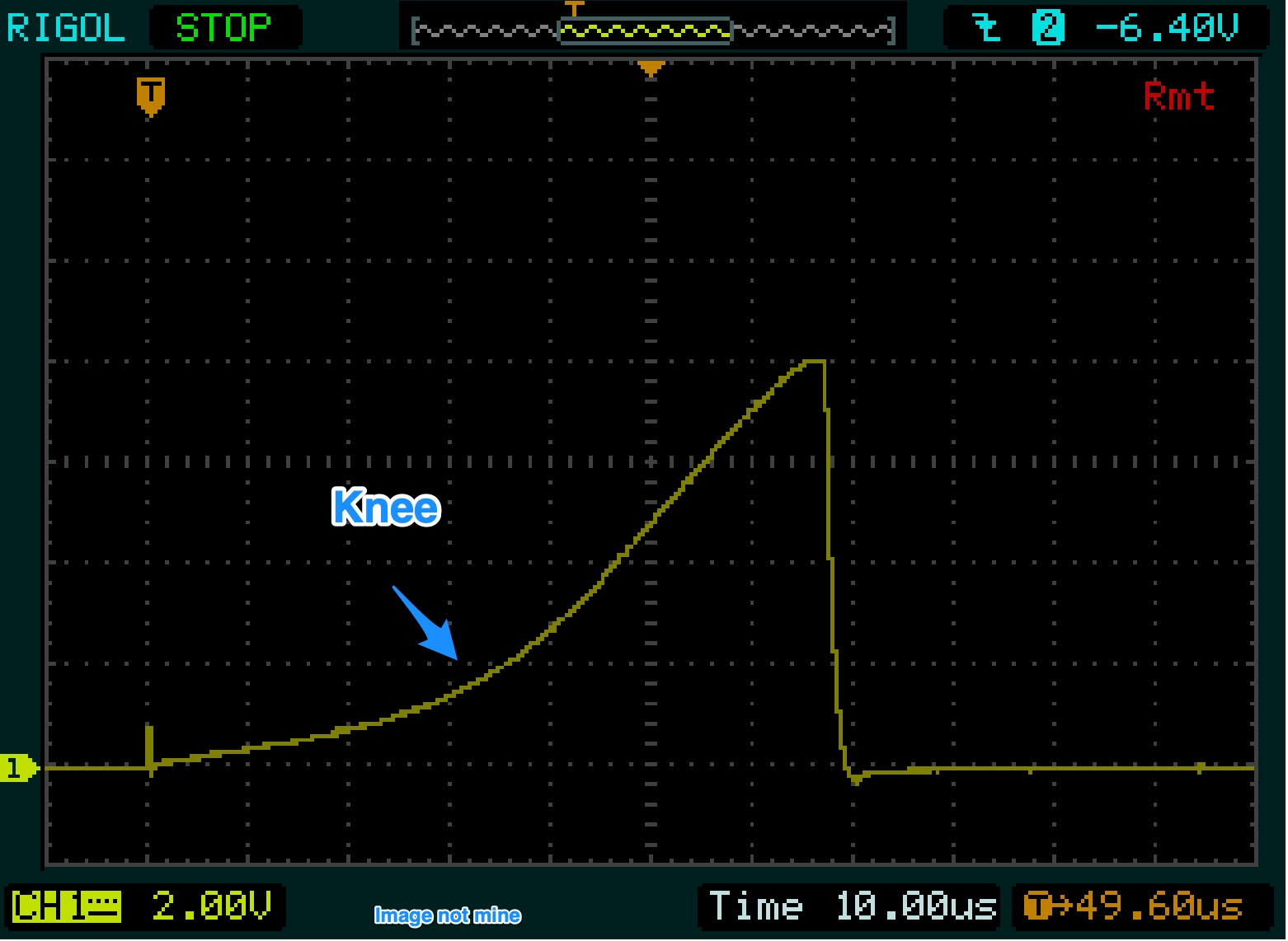
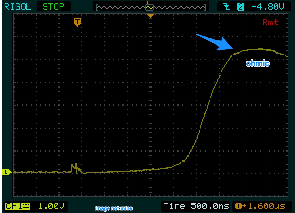
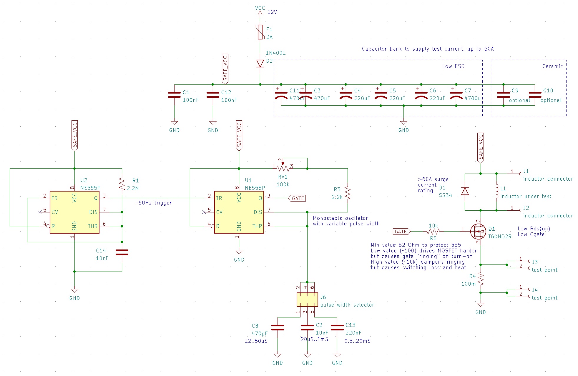
Once powered, the capacitor bank charges up. The circuit fires off a variable-width pulse into the MOSFET gate. MOSFET turns ON and short-circuits the inductor to the capacitor power bank. The current starts to rise linearly until the saturation point is reached. Once the inductor is saturated, it behaves like an ohmic piece of wire, and the current increases exponentially until the pulse is over, and the MOSFET is switched OFF. Saturation is a knee, not a sharp point. So you have some wiggle room in what current you designate as a "saturation current." Before the saturation point and including the "knee region," inductance will be higher than labeled. Once saturated sufficiently - inductance will drop.
This is how a regular plot should look like
This is how oversaturation, should look like
Commercial manufacturers pick the point where a power inductor loses 20-30% of its labeled inductance. One can safely operate inductors at x1.3-1.5 their knee point.
You take voltage drop measurements across 0.1 Ohm resistor, multiply by 10 and get current in Amps flowing through your inductor under test. I = V*10
You can also compute actual inductance be taking your supply voltage and dividing by the voltage slope.
L = Vs * Δt / ΔI.
See "sort-of" instructions video https://www.youtube.com/watch?v=3Y_WcuIenSM Notice that although their PCB is labeled 1us..50us. It's impossible to get a positive pulse width of less than 10uS with NE555. One can replace it with other astable timers ICs, but you need a separate MOSFET driving circuitry. NE555 raising and falling times ~350ns, with a max current of 200mA, which is not enough to quickly switch power MOSFETs ON/OFF. The MOSFET will be in its linear region for some time. Therefore the trigger pulse is set to ~50Hz, letting MOSFET cool down between pulses. Also, notice that the current sense shunt, capacitor bank ESR and traces resistance limits max current to ~56A. You would want to rig some sort of replacable solder-pads on the top of the PCB, so you can finger-press small SMD inductors to it and solder large ones to take measurements. There are header holes for this.
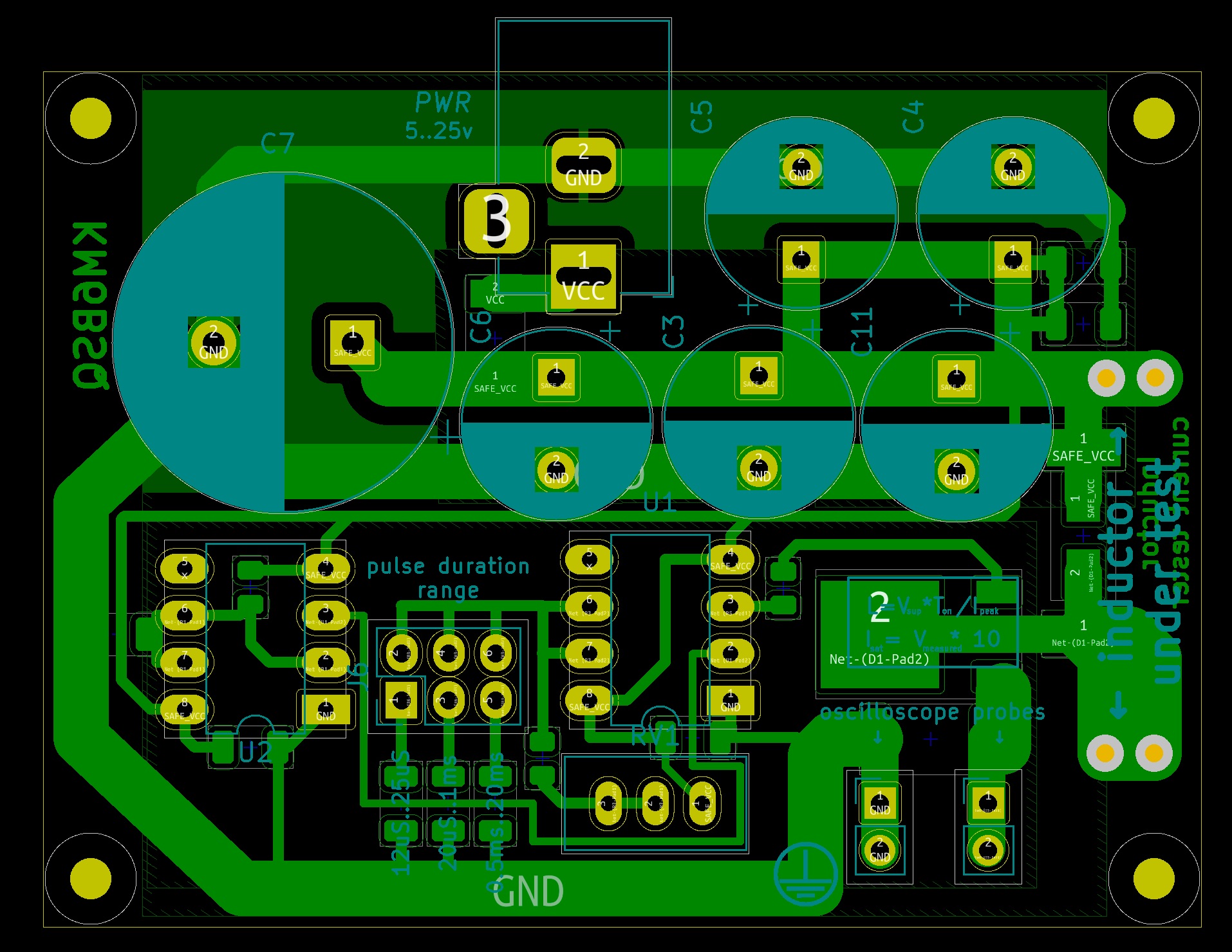
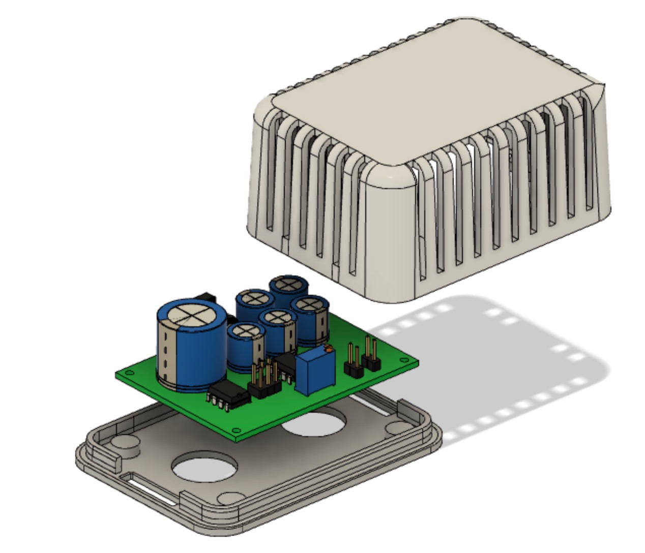
PCB Thermal Heat Flow Analysis
NE555 is a compromise for this project purpose, you need two of them to deliver a short pulse, but it can also source 200ma current by itself. An alternative design is to use a cheap MCU and a MOSFET driver. Same PCB footprint, but better timing (no need to mess around with jumpers) and higher currents to turn the MOSFET on and off. High gate current also means "ringing" on MOSFET turn on, which in turn manifests itself as current measurements ringing. For large inductors it is OK, for small (SMD) it might be hard to take measurements. With a better MCU one can even do automatic pulse control. This gets complex fast. 16 MHz Arduino is ~ 100uS per ADC sample.
For a 16 MHz Arduino the ADC clock is set to 16 MHz/128 = 125 KHz. Each conversion in AVR takes 13 ADC clocks so 125 KHz /13 = 9615 Hz.
As soon as you consider a fast external ADC, you start worry about crystal clock-jitter, temperature drift and SPI speed.
| Qty | Value | Footprint | References |
|---|---|---|---|
| 4 | MountingHole | MountingHole:MountingHole_2.2mm_M2 | H1, H2, H3, H4 |
| 3 | 220uF | Capacitor_THT:CP_Radial_D10.0mm_P5.00mm | C4, C5, C6 |
| 2 | 100nF | Capacitor_SMD:C_1206_3216Metric | C1, C12 |
| 2 | 10nF | Capacitor_SMD:C_1206_3216Metric | C2, C14 |
| 2 | 470uF | Capacitor_THT:CP_Radial_D10.0mm_P5.00mm | C3, C11 |
| 2 | NE555P | Package_DIP:DIP-8_W7.62mm | U1, U2 |
| 2 | inductor connector | Connector_Wire:SolderWirePad_1x01_SMD_2x4mm | J1, J2 |
| 2 | optional | Capacitor_SMD:C_1206_3216Metric | C9, C10 |
| 2 | test point | Connector_PinHeader_2.54mm:PinHeader_1x02_P2.54mm_Vertical | J3, J4 |
| 1 | 100k | Potentiometer_THT:Potentiometer_Bourns_3296W_Vertical | RV1 |
| 1 | 100m | Resistor_SMD:R_2512_6332Metric | R4 |
| 1 | 1N4001 | Diode_SMD:D_MELF | D2 |
| 1 | 2.2M | Resistor_SMD:R_0805_2012Metric | R1 |
| 1 | 2.2k | Resistor_SMD:R_0805_2012Metric | R3 |
| 1 | 220nF | Capacitor_SMD:C_1206_3216Metric | C13 |
| 1 | 2A | Resistor_SMD:R_2512_6332Metric | F1 |
| 1 | 4700u | Capacitor_THT:CP_Radial_D18.0mm_P7.50mm | C7 |
| 1 | 470pF | Capacitor_SMD:C_1206_3216Metric | C8 |
| 1 | 62 | Resistor_SMD:R_0805_2012Metric | R5 |
| 1 | IN | Connector_BarrelJack:BarrelJack_Horizontal | J5 |
| 1 | LOGO | LOGO | G*** |
| 1 | SS34 | Diode_SMD:D_SMA | D1 |
| 1 | T60NO2R | Package_TO_SOT_SMD:TO-252-2 | Q1 |
| 1 | pulse width selector | Connector_PinHeader_2.54mm:PinHeader_2x03_P2.54mm_Vertical | J6 |
baldengineer/bit-preserve
Project for capturing vintage, classic, aka old computer schematics in KiCad.

The-Invent0r/8-bit-Computer-PCB
These are the KiCAD files for my 8-Bit Computer.

DarcyJProjects/touchtone555
An open-source DIY, NE555-based analogue synthesizer - play notes with a stylus


benjiaomodular/SynthCard
I designed this project with the help of PCBWay. You can get a copy of these cards through the PCBWay Shared Projects page.

fortinsylvain/MyCpu
Home brew CPU Hardware with 1-bit ALU implementation using 74LSxx, a micro-code and assembler coded in C#.

hackup/C128Diag
Replica of the Commodore C128 Diagnostic Test cartridge Assy No. 325093-01.
It measures 62.5 × 46.2 mm and has 4 copper layers, 1.6 mm thick.
36 parts, built around the NE555P and SS34. The full list of its parts is on this page, with links to each part's symbol and footprint where PCBKit's library has them.
From the ikatkov/inductor-tester repository on GitHub, at the commit this page was made from: the board is main.kicad_pcb and its schematic main.kicad_sch. PCBKit opens the board in the browser, with nothing to install.
Its repository states no licence, so its author keeps all rights: ask ikatkov before reusing the design.