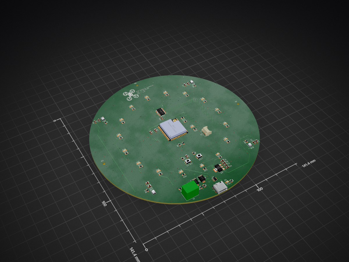
Celem projektu jest integracja elektroniki, zasilania i czujników w jednym module oraz ograniczenie problemów z połączeniami przewodowymi, które występowały na etapie prototypowania.
Kolko 4layer is an open-source printed circuit board by Igur7, from the Igur7/AngleCircle repository on GitHub. It is a 4-layer board of 50 × 50 mm with 85 parts on 91 nets, routed with 1,233 tracks and 389 vias.
It is built around the ESP32-S3-WROOM-1-N8, 74HC4067PW-Q100J and AMS1117-3.3, with the USBLC6-2SC6 and SPH0645LM4H-B among its other parts. Its parts include 31 resistors, 21 diodes, 16 capacitors, 4 ICs and 3 connectors. It belongs with the ESP32 boards of this library.
AngleCircle — czterowarstwowa płytka PCB do lokalizacji dźwięku
AngleCircle to projekt okrągłej, czterowarstwowej płytki PCB, opracowywanej w KiCadzie do systemu lokalizacji kierunku źródła dźwięku. System wykorzystuje ESP32-S3 i cztery cyfrowe mikrofony MEMS I²S, rozmieszczone wokół płytki.
Celem projektu jest integracja elektroniki, zasilania i czujników w jednym module oraz ograniczenie problemów z połączeniami przewodowymi, które występowały na etapie prototypowania.
Założenia projektowe
Okrągła geometria płytki dostosowana do układu czterech mikrofonów.
Cztery warstwy miedzi umożliwiające rozdzielenie sygnałów, zasilania oraz pól masy.
Projektowanie ciągłych ścieżek prądu powrotnego i odpowiedniego połączenia obszarów GND za pomocą przelotek.
Prowadzenie linii I²S (BCLK, WS/LRCLK i DATA) z uwzględnieniem integralności sygnałów i geometrii połączeń.
Integracja z mikrokontrolerem ESP32-S3 oraz elementami elektroniki pomocniczej.
Przygotowanie schematu i layoutu PCB w KiCadzie.
Architektura mikrofonów
Cztery mikrofony tworzą dwie pary pomiarowe, używane do estymacji opóźnienia nadejścia dźwięku (TDOA):
text
         GÓRA

  MIC 1          MIC 2
 (lewy górny)  (prawy górny)
       \        /
        \      /
         \    /
          \  /
           \/
           /\
          /  \
         /    \
        /      \
       /        \
  MIC 3          MIC 4
 (lewy dolny) (prawy dolny)

         DÓŁ

 I²S1: MIC 1 + MIC 4
 I²S0: MIC 2 + MIC 3
Przyjęta w firmware koncepcja pomiaru łączy mikrofony w dwie przekątne. Każda przekątna jest obsługiwana przez oddzielny kontroler I²S, aby zapewnić synchronizację wewnątrz pary pomiarowej.
It measures 50 × 50 mm and has 4 copper layers, 1.6 mm thick.
What parts does the Kolko 4layer use?
85 parts, built around the ESP32-S3-WROOM-1-N8, 74HC4067PW-Q100J, AMS1117-3.3 and USBLC6-2SC6. The full list of its parts is on this page, with links to each part's symbol and footprint where PCBKit's library has them.
Where can I download the Kolko 4layer KiCad files?
From the Igur7/AngleCircle repository on GitHub, at the commit this page was made from: the board is PCB/kolko_4layer.kicad_pcb and its schematic PCB/kolko_4layer.kicad_sch. PCBKit opens the board in the browser, with nothing to install.
Can I use the Kolko 4layer design in my own project?
Its repository states no licence, so its author keeps all rights: ask Igur7 before reusing the design.
The project was executed in a team-based environment (5 members) with a strong focus on real-world system design practices, including modular architecture, hardware–software co-design, and scalable development.
A novel approach to enhancing silent speech recognition systems with a multiplexed star electrode array, developed for my final year dissertation at University College London (UCL).
Niphargus — a slim, indestructible wireless split keyboard. ESP32 + nRF24, wired fallback, and an emergency kit hidden behind the USB port. The successor to the Rouge-Gorge.