2 layers50 × 102 mm
Controller
ieb/windlasscontroller
Simple 2.4GHz long range windlass remote controller and base station
9 parts
 ieb/windlasscontroller
Simple 2.4GHz long range windlass remote controller and base station
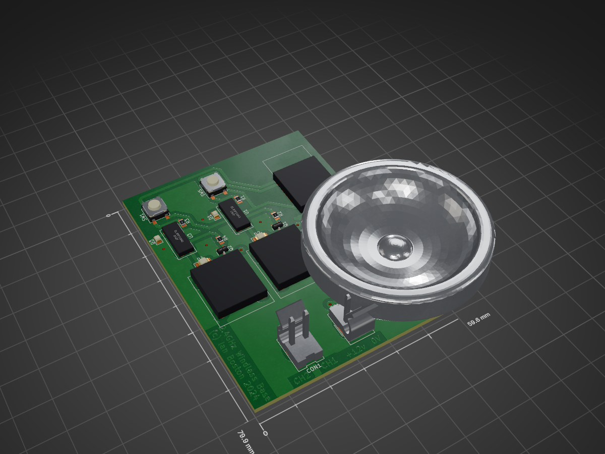
WindlassControl is an open-source printed circuit board by ieb, from the ieb/windlasscontroller repository on GitHub. It is a 2-layer board of 59.6 × 79.9 mm with 24 parts on 28 nets, routed with 210 tracks and 9 vias.
It is built around the AMS1117-3.3, BAS316 and MMBT5551L. Its parts include 6 ICs, 4 resistors, 4 diodes, 3 connectors and 2 capacitors.


I have found that wire windlass switches fail at when installed at the bow due to water ingress into the switches as do sockets. So 7 years ago I used a simple 433Mhz garage door controller as a remote windlass controller. However the remote controls are not easy to use being too small, and the range is typically less than 10m which is shorter than the boat making the controller unreliable.
This project uses a JDY-40 module (typical cost < $1) which can be configured as a remote 8 channel switch. It has a claimed range of 120m, tested at 60m and uses 2.4GHz. It sleeps automatically drawing 5uA when sleeping and requires almost no external components in the controller. The base uses a second JDY-40 module with opto couplers and a G1 transistor driving a relay. Remote is powered by a CR123A 3V lithium battery which should last several years even if left on sleeping. There is an on-off switch. No custom code, but the modules have to be programmed as transmitter and base with the same RF IDs. Code to do this is in setup.
There are 2 schematics, one for base and one for the controller, and designs for the case and base cases.
The PCBs are in KiCad, and were milled using pcb2gcode double sided with alignment, see createGCode.sh for the setup. Everything else is very standard.
| Qty | Value | Footprint | References |
|---|---|---|---|
| 2 | 10K | Resistor_SMD:R_0805_2012Metric_Pad1.20x1.40mm_HandSolder | R2, R4 |
| 2 | BAS316 | LED_SMD:LED_1206_3216Metric_Pad1.42x1.75mm_HandSolder | D2, D4 |
| 2 | C | Capacitor_SMD:C_1210_3225Metric | C1, C2 |
| 2 | EL B17 CO43 | iebSpecials:OptoIsoator4pin | U1, U3 |
| 2 | MMBT5551L | Package_TO_SOT_SMD:SOT-23 | Q1, Q2 |
| 2 | SW_Push | Button_Switch_SMD:SW_SPST_EVPBF | SW1, SW5 |
| 2 | ~ | iebSpecials:Relay Tongling | U4, U7 |
| 1 | 2.2K | Resistor_SMD:R_0805_2012Metric_Pad1.20x1.40mm_HandSolder | R3 |
| 1 | 22K | Resistor_SMD:R_0805_2012Metric_Pad1.20x1.40mm_HandSolder | R1 |
| 1 | AMS1117-3.3 | Package_TO_SOT_SMD:SOT-223-3_TabPin2 | U6 |
| 1 | LED | LED_SMD:LED_0805_2012Metric | D3 |
| 1 | LED | LED_SMD:LED_0805_2012Metric_Pad1.15x1.40mm_HandSolder | D1 |
| 1 | Power | Connector_Molex:Molex_KK-396_5273-02A_1x02_P3.96mm_Vertical | CON2 |
| 1 | Serial Interface | Connector_Harwin:Harwin_M20-89004xx_1x04_P2.54mm_Horizontal | J2 |
| 1 | Switched Out | Connector_Molex:Molex_KK-396_5273-02A_1x02_P3.96mm_Vertical | CON1 |
| 1 | prog | Jumper:SolderJumper-2_P1.3mm_Open_Pad1.0x1.5mm | JP2 |
| 1 | ~ | iebSpecials:Jdy40 | U2 |
It measures 59.6 × 79.9 mm and has 2 copper layers, 1.6 mm thick.
24 parts, built around the AMS1117-3.3, BAS316 and MMBT5551L. The full list of its parts is on this page, with links to each part's symbol and footprint where PCBKit's library has them.
From the ieb/windlasscontroller repository on GitHub, at the commit this page was made from: the board is WindlassControl.kicad_pcb and its schematic Controller.kicad_sch. PCBKit opens the board in the browser, with nothing to install.
Its repository states no licence, so its author keeps all rights: ask ieb before reusing the design.
ieb/windlasscontroller
Simple 2.4GHz long range windlass remote controller and base station

Neumi/fastLOGIC
An affordable Arduino-based board designed for straightforward (industrial) logic control, ideal for building small-scale automation and control solutions.


wolffshots/esp-ip
This project is a hardware solution that leverages the power of the ESP32 to bridge local communication interfaces, such as serial and (in the future) I2C, to a WiFi network.

eez-open/psu-hw
EEZ H24005 programmable bench power supply (powered by Arduino Due)

