2 layers70.6 × 28 mm
ModusBatteryMonitor
ieb/ModbusShunt
Modbus Battery monitor using IN219 Attiny3224 on a 100A 75mV shunt.
17 parts
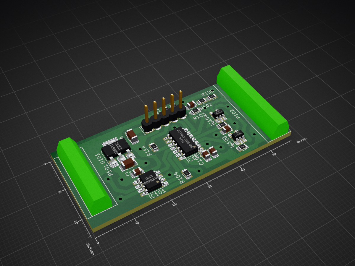
 ieb/BatterySensor1
A Modbus RTU Battery Current and Voltage sensor board based Attiny3224, MAX485, MAX9918 chips.
BatteryMonitorATTiny3224 is an open-source printed circuit board by ieb, from the ieb/BatterySensor repository on GitHub. It is a 2-layer board of 56.7 × 25.4 mm with 24 parts on 20 nets, routed with 265 tracks and 17 vias.
It is built around the ATTINY3224-SSU, MAX3485ED and RS485, with the AMS1117 among its other parts. Its parts include 9 resistors, 7 capacitors, 5 ICs and 3 connectors. It belongs with the sensors and measurement boards and the AVR (ATmega, ATtiny) boards of this library.


Aim is to create a low power smat shunt batter sensor reporting volage, current and temperatire over ModbusRTU.
Shunt is measured using a MAX9918 shut amplifier amplifying 48x a 75mV/100A shunt scaled down to 50mV to keep the MAX9918 input optimal. Temperature by a 10K NTC read by ADC using an interpolation table. Voltage by direct ADC with a voltage divder RS485 by MAX485
Modbus RTU - bigendian
Stored in EEPROM, which is typically reset on a firmware upgrade.
| Offset | Name | type | details |
|---|---|---|---|
| 0 | Device Adddress | int16 | 1-254 modbus address, default is 2 |
| 1 | Voltage offset adjustment | int16 | Offset in 0.1mv steps eg 10 = 1mV |
| 2 | Voltage scale adjustment | int16 | scale in 1/10000th eg 10000 = 1x |
| 3 | Current offset adjustment | int16 | offset in 0.1mA steps eg 10 = 1mA |
| 4 | Current scale adjustment | int16 | scale in 1/10000th eg 10000 = 1x |
| 5 | Temperature offset adjustment | int16 | offset in C in 1/1000th eg 1000 = +1C |
| 6 | Temperature scale adjustment | int16 | scale in C in 1/1000th eg 1000 = 1x |
| 7 | Serial Number | int16 | Device serial number, once set cannot be changed |
| Offset | Name | type | details |
|---|---|---|---|
| 0 | Voltage | int16 | Units 0.01V |
| 1 | Current | int16 | Units 0.01A |
| 2 | Temperature | int16 | 1 = 0.01C |
| 1001 | Recieved | uint16 | count of frames recieved |
| 1002 | Sent | uint16 | count off frames send |
| 1003 | Errors Recieved | uint16 | count off frames recieved with errors |
| 1004 | Ignored | uint16 | count off frames dropped |
| 1005 | Errors Sent | uint16 | count off error frames send |
Exceptions are reported as per ModbuRTU Spec.
Platform ATTiny8224 Could have also used a ATTiny84, but this has no uarts and requires ICSP programming. Programmming using jtag2udpi on an Arduino Uno with avrdude.conf setup for the ATTiny8224, running at 5V.
The ATTiny ADC in 16bit using 4096 refrence through aa 32K/10K divider, gives withing 10mv of a 4 digit multi meter after calibration setting (0.9954 register 2 set to 9954). Hard to tell which is more accutage, probably the ADC. Voltage is stable with the LSB changing +- 1 or 2.
Multiple frustrating attempts with a current amplifier, eventually abandoned.
The originam MAX9918 had an unstable 75mV offset from the reference resistors at 0A which would not go, chip might have been damaged during soldering or the EP ground plane was not good enough.
2x INA169 that I had from years ago could not be made to amplify the input correctly at the required 47x gain. Looking back I had tried INA169 before and had problems eventually abandoning.
Now trying the Attiny3224 ADC + PGA at 16x which measures down to 0.0019mV perbit below 64mV differntial on the 16bit range with a 1024mV refrence, however this might really be 0.015625mV resolution as the 16 bit is oversampling 12bit. If it is, this represents a resolution of +-20mA which is perfectly reasonable for a 100A/75mV shunt. Quick testing indicates this is stable and repeatable with 10R on the input lines for protection from misconnection and 100nF accross the ADC inputs to remove high frequency components.
If that fails I will use one of the Alegro Hall chips, althought I prefer the simplicity of a shunt.
Performed over serial on the second uart at 115200 baud. Modbus is at 9600 baud 8N1
Building with DEVMODE (see main.cpp) defined allows the rs485 serial to be diverted to Serial1 and test patterns to be pasted from testpatterns.txt over the monitoring serial line.
Testing can be done with
pio run -e native which produces a native binary then
cat testpattern.txt | ./.pio/build/native/programWhich checks exercises the RS485 protocol using test patterns checking the response.
Currently using jtag2udpi, via an Uno, but setting fuses seems hard Needs a modified avrdude.conf file to add support for the attiny3224 pio run -t fuse -e attiny3224 does appear to work.
Fuses must be set to ensure the chip clock speed matches the compiled code. This only needs to be done once per chip. It its not done the serial output doesnt sync with the baud rate and garbage is seen on the serial line.
pio run -t fuses -e attiny3224Looking at megaTinyCore support in the Arduino IDE using SerialUDPI is much better and more advanced.
pio run -t upload -e attiny3224 works ok for the moment.
For full details see the pcb/* In outline.
        ------------------------------------------
        | a           1 2 3 4 5                 A|
        | b   MAX                      MAX      B|
        | c   RS485   Atting3224       9918     C|
        | d                                     D|
        |     AMS1117                           E|
        ------------------------------------------

        a = GND
        b = Vin (12v)
        c = RS485 A
        d = RS485 B

        1 = GND
        2 = +5V
        3 = UDPI
        4 = Debug RX
        5 = Debug TX

        A = Battery +Ve
        B = Shunt -
        C = Shunt +
        D = GND
E = NTCin testclient/ requires python3. install with
pip install -r requirements.txtrun with
python3 batterymon.py| Qty | Value | Footprint | References |
|---|---|---|---|
| 5 | 10K | Resistors_SMD:R_0805 | R101, R103, R104, R105, R108 |
| 3 | 100nF | Capacitors_SMD:C_0805 | C105, C106, C109 |
| 2 | 10uF | Capacitors_SMD:C_1206 | C101, C104 |
| 2 | 47K | Resistors_SMD:R_0805 | R112, R113 |
| 2 | INA169 | TO_SOT_Packages_SMD:SOT-23-5_HandSoldering | IC103, IC104 |
| 1 | 1nF | Capacitors_SMD:C_0805 | C107 |
| 1 | 22K | Resistors_SMD:R_0805 | R102 |
| 1 | 270R | Resistors_SMD:R_0805 | R114 |
| 1 | AMS1117 | TO_SOT_Packages_SMD:SOT-223-3Lead_TabPin2 | U101 |
| 1 | ATTINY3224-SS | Housings_SOIC:SOIC-14_3.9x8.7mm_Pitch1.27mm | IC102 |
| 1 | Bat | Connect:bornier5 | P102 |
| 1 | C | Capacitors_SMD:C_0805 | C108 |
| 1 | MAX3485E | Housings_SOIC:SOIC-8_3.9x4.9mm_Pitch1.27mm | IC101 |
| 1 | Prog | Pin_Headers:Pin_Header_Straight_1x05 | P103 |
| 1 | RS485 | Connect:bornier4 | P101 |
It measures 56.7 × 25.4 mm and has 2 copper layers, 1.6 mm thick.
24 parts, built around the ATTINY3224-SSU, MAX3485ED, RS485 and AMS1117. The full list of its parts is on this page, with links to each part's symbol and footprint where PCBKit's library has them.
From the ieb/BatterySensor repository on GitHub, at the commit this page was made from: the board is pcb/BatteryMonitor/BatteryMonitorATTiny3224.kicad_pcb. PCBKit opens the board in the browser, with nothing to install.
Its repository states no licence, so its author keeps all rights: ask ieb before reusing the design.
ieb/ModbusShunt
Modbus Battery monitor using IN219 Attiny3224 on a 100A 75mV shunt.

anyshake/explorer
🌏 Detecting seismic wave using 3 geophones and 3-axis accelerometer, pack & send data to AnyShake Observer over RS232 / RS485 serial.

fraxinas/DoorBirdPico
A custom Raspberry Pi Pico PCB design and code to add functionality to the DoorBird Voip entryphone.

austinscreations/Oxrs-Black
a custom rack controller that is based of the rack32 but includes some upgrades and major changes

bclswl0827/openstation
An open source, cross-platform, easy-to-use satellite automatic tracking system with hardware & software solutions.


NGOQUOC98/ESP32_MODBUS_PCB_MASTER
This project was in development phase - we will remove this remark after release

danielmcmillan/irrigation-system
Hardware and software for irrigation control and monitoring