


2 layers73 × 47.5 mm

 iandchasse/silkscreen-light-attachment
Clip-on warm/cool reading light for the Silkscreen e-reader; plugs into the main board's expansion header through the top of the stock 4.26in case
Silkscreen light attachment is an open-source printed circuit board by iandchasse, from the iandchasse/silkscreen-light-attachment repository on GitHub, published under the CERN-OHL-S-2.0 licence. It is a 2-layer board of 65 × 17 mm with 16 parts on 13 nets, routed with 41 tracks and 1 via.
It is built around the HL-A-3014H421W-S1-08HL-HR3, CRCW0805200RFKEAHP and HC-PZ254-11.5L-1X1PZ, with the HC-PZ254-11.5L-1X2PZ among its other parts. Its parts include 10 diodes, 2 resistors and 2 connectors.


[!IMPORTANT] AI-generated design. This is an accessory, not part of the Silkscreen PCBA.
This light attachment was designed with substantial AI assistance: its board and housing are generated by code written with AI tools. It serves two purposes: a test of what AI tools can and cannot do with a simple electrical design like an LED strip, and a functional accessory for the base Silkscreen PCBA. The Silkscreen PCBA itself (silkscreen-pcb) was not AI-generated.
See Silkscreen's AI disclosure: https://silkscreenreader.com/ai
A clip-on warm/cool reading light for the Silkscreen e-reader. It is a small cap that pushes onto the top of the stock case. Three header pins go down through the opening the case already has in its top wall and plug into the main board's expansion header, the 12-pin socket on its top edge (labelled J6 on the board). The case is not modified.
Status (2026-10-21): the rev B board and the rev B housing are built and work. Pins line up with the expansion header, the cap fits the 4.26" case and snaps on, and the light works. The rev C housing (enclosing hood, rounder brow, rabbeted seam) is checked in CAD only and has not been printed yet. The board is unchanged (rev B). The rev B prints are in
archive/rev-B-housing/print/.Cheapest first step: print the two parts (about 36 min, 8.6 g; rev C, with the enclosing hood) and try the empty base on your case. It has no metal, so that is safe.
| On the stock case (render) | Exploded | Light board, LED side (faces the case) |
|---|---|---|
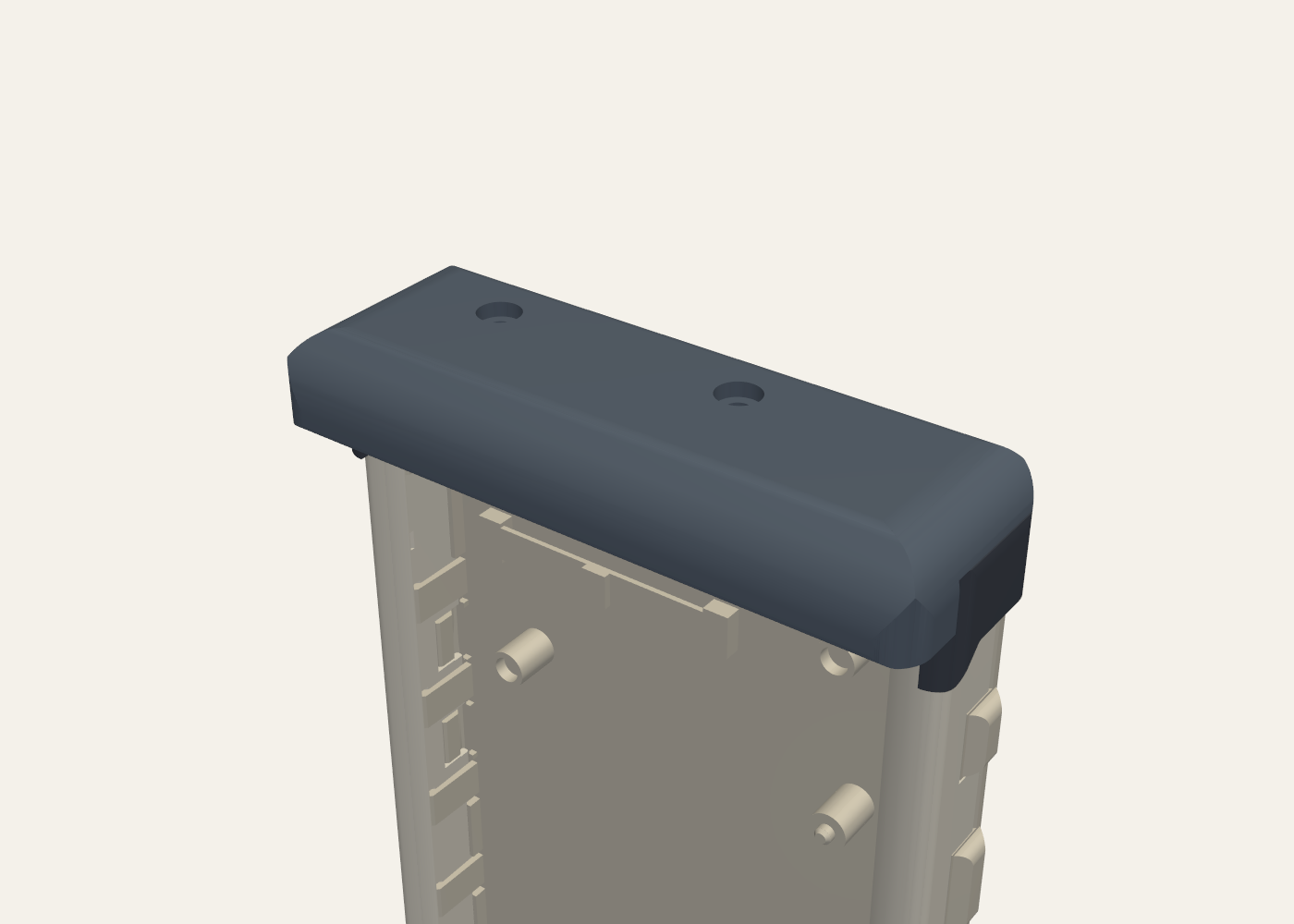 | 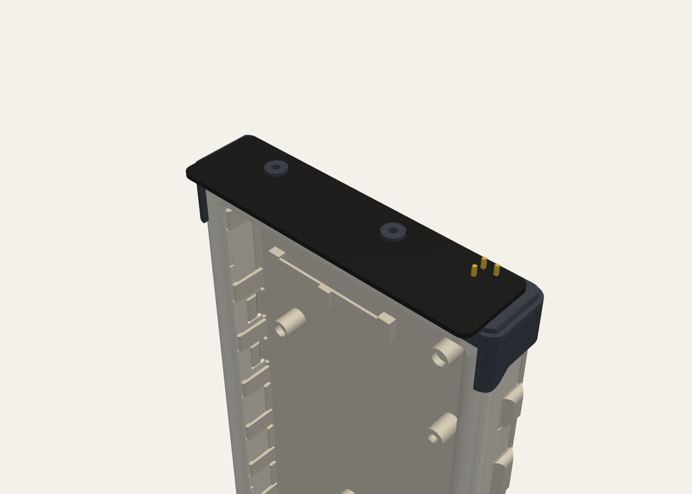 | 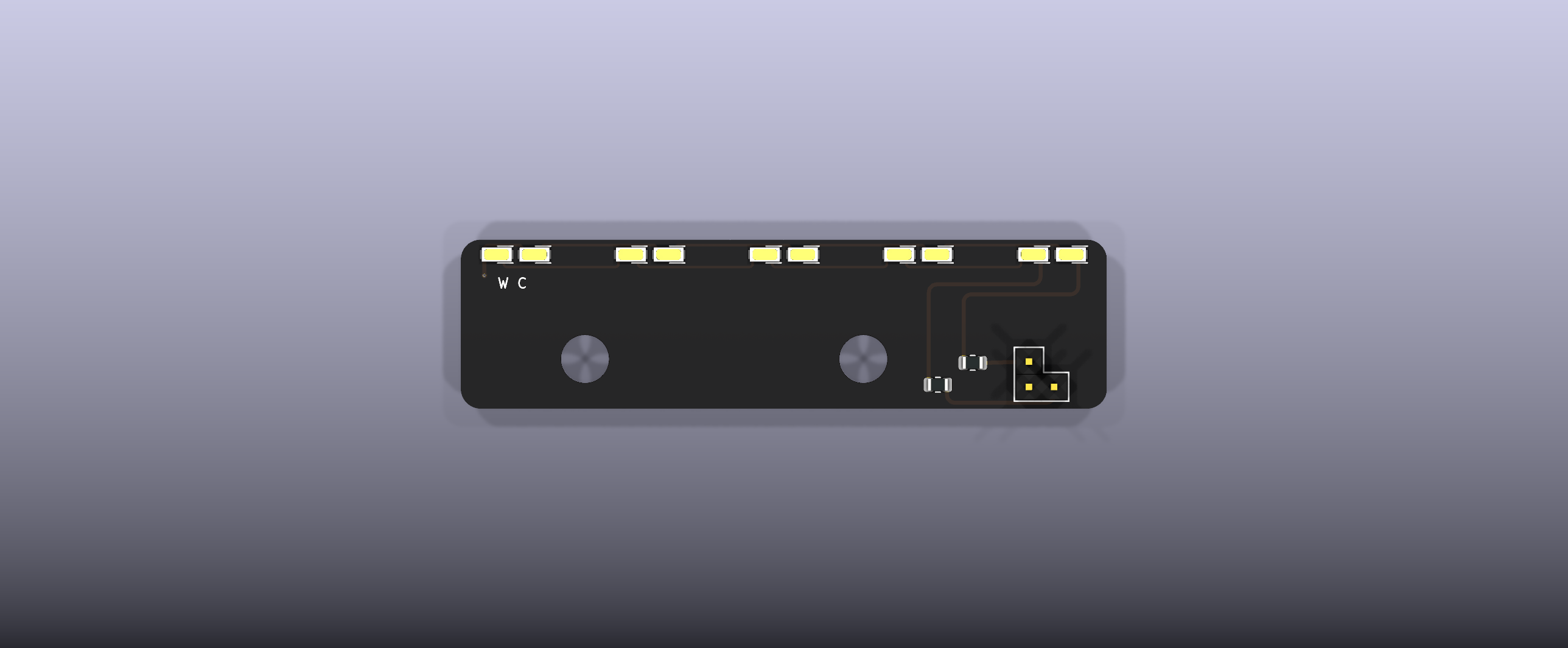 |
More renders: front, right side, section through the expansion header, section through an LED, section through a screw boss, board top side.
LCSC stock on 2026-09-25 is in parentheses. All five parts are JLC Extended parts.
| Item | Qty | Notes |
|---|---|---|
| Light PCBA | 1 | 2 layers, 1.0 mm, 65.0 × 17.0 mm. Everything sits on one side. The JLC files hold all 14 parts: the 12 SMD parts plus the 2 headers (through-hole; untick them at JLC to solder them yourself): warm LED C210340 × 5 (102,969), cool LED C210343 × 5 (40,519), 200 Ω Vishay CRCW0805200RFKEAHP C5972814 × 2 (2,477). See ORDERING |
Pin header, 1 × 2 (J1 in the BOM) | 1 | Hong Cheng HC-PZ254-11.5L-1x2PZ, LCSC C27985187 (24,852). Fitted by JLC or by you |
Pin header, 1 × 1 (J2 in the BOM) | 1 | Hong Cheng HC-PZ254-11.5L-1x1PZ, LCSC C27985186 (10,775). Fitted by JLC or by you |
| Printed base and lid | 1 each | PETG (PLA for a trial), no supports. Base 20 min 20 s, 3.25 g; lid 15 min 50 s, 5.32 g (Elegoo CC2, 0.4 nozzle, 0.20 mm). Print the lid in a light colour (white, light grey, silver silk): the hood is a reflector, and a black lid absorbs the light it would add. Optional: turn on Detect thin wall so the 0.2 mm stop under each screw hole prints |
| Screws, M2 × 3 pan head | 2 | ISO 7045 (cross) or ISO 14583 (Torx), machine or thread-forming. Not longer than 3 mm |
Tools: a soldering iron, a spare 2.54 mm 2-row female header (a jig to hold the pins square), a small screwdriver and a multimeter. A current-limited bench supply is useful for the optional bench test.
Full steps: ASSEMBLY.
Details and the bench test: SAFETY-AND-TEST.
Bright near the top of the page and fading down it: 10 mm down the page gets about 12 × the light of the page middle, the bottom edge about 1/5 of it. Fine as a reading light, not an even frontlight. The front hood hides the LEDs and the board edge from your eyes and, on a light-coloured lid, bounces a little more light down the page (about +12 % in the lower half, +14 % mid-page, +24 % at the top; none on a black lid). Shaping the light further is a job for printed changes to the cap. Numbers: DESIGN.
| Doc | What it covers |
|---|---|
| docs/ORDERING.md | JLCPCB PCB and assembly fields, the placement-preview check, headers, screws, printing |
| docs/ASSEMBLY.md | Soldering the headers, putting the cap together, fitting it on the reader |
| docs/SAFETY-AND-TEST.md | The rules, a bench test of the bare board, what the reader should show |
| docs/DESIGN.md | Why it is built this way, electrical and optics numbers, known limits |
| docs/FIRMWARE-NOTES.md | Recommended firmware changes (enable pulse, load check). The firmware is not changed |
| pcb/docs/jlc-notes.md | Generated JLC order notes |
| pcb/docs/design_summary.md | Generated electrical and placement summary |
| housing/out/REPORT.md | Generated housing check report |
| design/DESIGN-SPEC-revB.md | The rev B contract |
| Path | What it is |
|---|---|
pcb/ | Generated KiCad 9 project. pcb/tools/ generates everything; do not edit the .kicad_* files by hand |
pcb/production/ | Gerber zip, bom.csv, jlc_bom.csv, jlc_cpl.csv, STEP/STL (including the PCBA in the case frame) |
pcb/docs/ | Schematic and layout PDFs, renders, design_summary.md, jlc-notes.md, gate reports, part evidence |
housing/src/ | CadQuery source for the base and lid, and the fit checks |
housing/out/ | Print files (print/base.stl, lid.stl, .step, plate.3mf), REPORT.md, checks.json, renders, slicer report |
design/ | The rev B contract (DESIGN-SPEC-revB.md), the stock-case mechanical spec, and the rev A design notes and reviews |
research/ | Source research: the expansion header (J6), electrical and mechanical, and the stock case |
tools/ | Optics ray-trace scripts (optics_sim.py is the one rev B uses; the rev A rod-lens scripts are in archive/rev-A-rod-lens/tools/) |
workflows/ | Local only, not tracked: the scripts that drove the design runs |
archive/rev-A-rod-lens/ | Rev A (rod lens, carrier, clip and cover): its PCB, housing and docs. Not current |
archive/rev-B-housing/print/ | The rev B printed parts (the ones first printed: short visor, open ends, flat seam). Superseded by the rev C housing in housing/out/print/ |
enclosures/silkscreen-enclosure-claude/ | Local only, not tracked: the old rev K case copy. The checks now read the consolidated 4.26" case instead (see Housing below) |
PCB. Close KiCad first: the scripts refuse to write while a *.lck file exists.
cd pcb
"C:\Program Files\KiCad\9.0\bin\python.exe" tools\generate.py
"C:\Program Files\KiCad\9.0\bin\python.exe" tools\make_outputs.py
make_outputs.py runs every gate first and writes production/, docs/ and build/geometry.json only if all pass.
Housing. Use a Python 3.11 venv made from silkscreen-enclosures' enclosures/case-426/requirements.txt (CadQuery, trimesh, manifold3d). Run the PCB step first: the housing reads pcb/build/geometry.json and the case it fits: the 4.26" standard (strip-less) case, whose tub.stl + lid.stl are copied into housing/reference/case-426-standard/ (from silkscreen-enclosures, enclosures/case-426/out/standard/; see PROVENANCE.md there). Set SILKSCREEN_CASE_OUT to check against another build, e.g. a fresh one in ../silkscreen-enclosures/enclosures/case-426/out/standard/. The 3.68" reader's trimmed board has no expansion header, so it is not supported.
cd housing
python src\build.py       # --no-render for a quicker run
build.py builds both parts, runs the checks, writes out/ and exits with code 1 on any failed check. Optional: python src\optics_report.py (system Python) refreshes out/optics.json, and src\slice_check.py (same venv, needs OrcaSlicer) refreshes the slice report; run build.py again afterwards to fold both into REPORT.md.
Designed by Ian Chasse (idc LLC) as a companion to silkscreen-pcb. The generator structure comes from the sibling project silkscreen-light-strip. The stock case is the 4.26" case of silkscreen-enclosures (its top is unchanged since rev K).
CERN-OHL-S-2.0, © 2026 idc LLC. See LICENSE and NOTICE. The KiCad library parts in pcb/lib/ keep their own terms (listed in NOTICE). The third-party evidence behind the part choices (a datasheet page, LCSC/EasyEDA part data) is kept locally in pcb/docs/sources/ and is not published.
| Qty | Value | Footprint | References |
|---|---|---|---|
| 10 | HL-A-3014H421W-S1-08HL-HR3 | silkscreen-light-attachment:LED_3014_HONGLI_HL-A-3014H421W | D1, D2, D3, D4, D5, D6, D7, D8, D9, D10 |
| 2 | CRCW0805200RFKEAHP | silkscreen-light-attachment:R_0805_2012Metric | R1, R2 |
| 1 | HC-PZ254-11.5L-1x1PZ | silkscreen-light-attachment:J6_PLUG_1x1_P11 | J2 |
| 1 | HC-PZ254-11.5L-1x2PZ | silkscreen-light-attachment:J6_PLUG_1x2_P5_P6 | J1 |
| 1 | M1 housing boss (dia 4.40) + ST2.2 screw | silkscreen-light-attachment:NPTH_4.80mm | H1 |
| 1 | M2 housing boss (dia 4.40) + ST2.2 screw | silkscreen-light-attachment:NPTH_4.80mm | H2 |

google/mozc-devices
Circuit diagrams and firmware source code for Gboard DIY keyboards

conorpp/u2f-zero
U2F USB token optimized for physical security, affordability, and style

rusefi/rusefi
rusefi - GPL internal combustion engine control unit

VoronDesign/Voron-Hardware
Cool Hardware designed by the Voron Design group

hoglet67/RGBtoHDMI
Bare-metal Raspberry Pi project that provides pixel-perfect sampling of Retro Computer RGB/YUV video and conversion to HDMI

hackclub/OnBoard
💡 Join 1,000 teenagers and make your first PCB with a $100 grant!

It measures 65 × 17 mm and has 2 copper layers, 1 mm thick.
16 parts, built around the HL-A-3014H421W-S1-08HL-HR3, CRCW0805200RFKEAHP, HC-PZ254-11.5L-1X1PZ and HC-PZ254-11.5L-1X2PZ. The full list of its parts is on this page, with links to each part's symbol and footprint where PCBKit's library has them.
From the iandchasse/silkscreen-light-attachment repository on GitHub, at the commit this page was made from: the board is pcb/silkscreen-light-attachment.kicad_pcb and its schematic pcb/silkscreen-light-attachment.kicad_sch. PCBKit opens the board in the browser, with nothing to install.
Its repository publishes it under the CERN-OHL-S-2.0 licence: you may reuse it on that licence's terms (keep the author's notice, and for a copyleft licence share your changes alike).