4 layers59.9 × 66.5 mm

 iamjackchen/SLLed
A decorative lighting piece I designed as a gift for an old ex. That relationship has ended, so I thought I could make it a part of my public portfolio and put it to use in finding a job (help).
ProjectSLL is an open-source printed circuit board by iamjackchen, from the iamjackchen/SLLed repository on GitHub. It is a 2-layer board of 100 × 100 mm with 61 parts on 58 nets, routed with 290 tracks and 15 vias.
It is built around the ATMEGA16U2-AU and AMS1117-5.0. Its parts include 24 resistors, 18 diodes, 9 capacitors, 3 switches and 2 ICs. It belongs with the AVR (ATmega, ATtiny) boards of this library.


A decorative lighting piece I designed as a gift for an old ex. That relationship has ended, so I thought I could make it a part of my public portfolio and put it to use in finding a job (help).
The project is called "SLLed" because the intended recipient had supposedly caught me talking about singly-linked lists in my sleep. wtaf.
Inspired by https://www.instructables.com/DIY-LED-heart/.
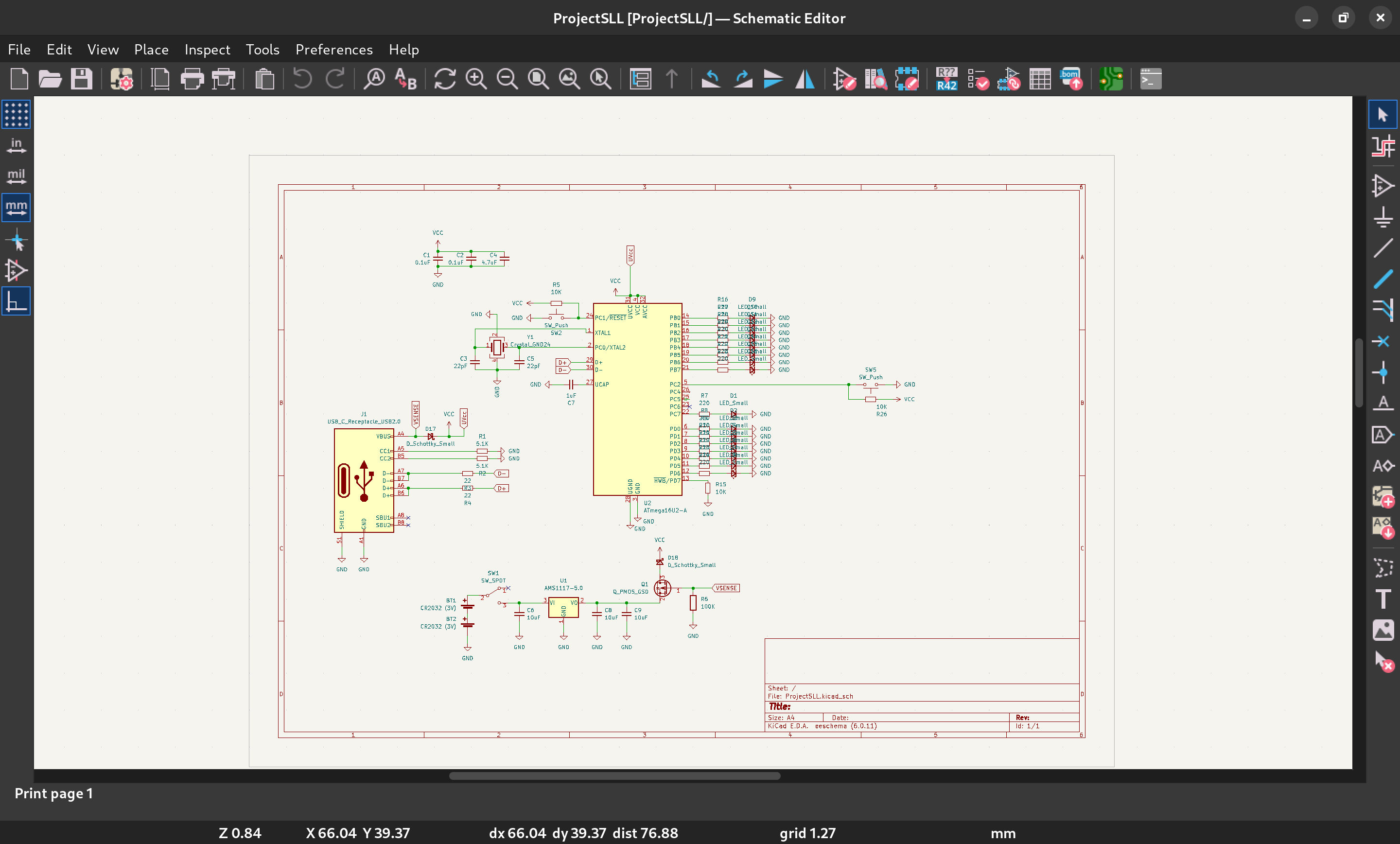
I first started by building a schematic in KiCAD. Some design considerations:
I was at uni and didn't have access to my usual soldering equipment, so I had to get my PCB assembled by its manufacturer. This meant that my component selection was restricted to what the manufacturer had available.
I also didn't have access to any mcu programming tools, so I wanted this module to be USB-programmable for ease of development. USB-C because, c'mon guys, it's 2023.
For the MCU I settled for the ATMega16U2, which is from the family of microcontrollers used in the classic Arduino line (the commonly-used 32U4 was out of stock).
I added a 16MHZ crystal should I choose to implement some form of USB connectivity with a host device in the future (for which the 16U2's internal crystal would be insufficient).
I also designed a very simple MOSFET-based power-switching circuit so that this module can be powered both via battery and USB.
The final schematic may be found here.
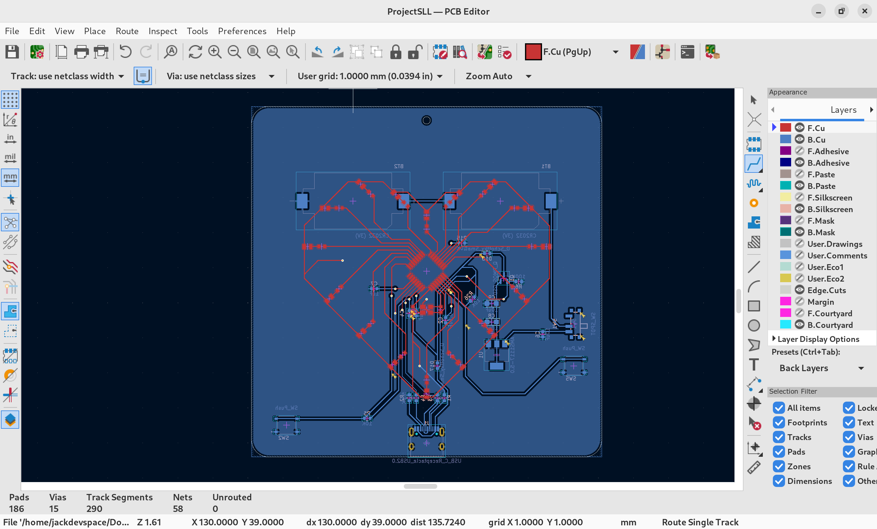
I then assigned footprints to components and build a quick layout. Some design considerations:
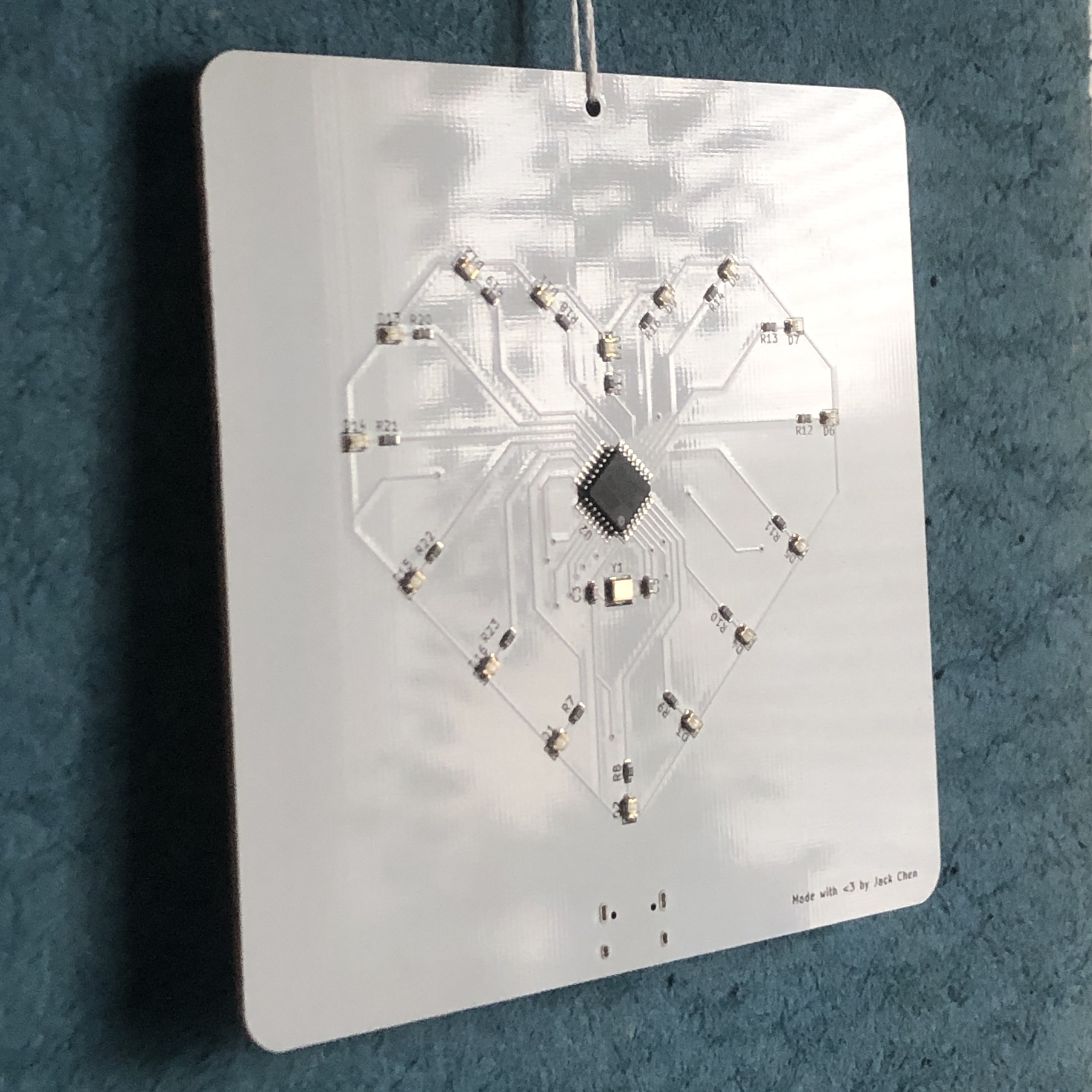
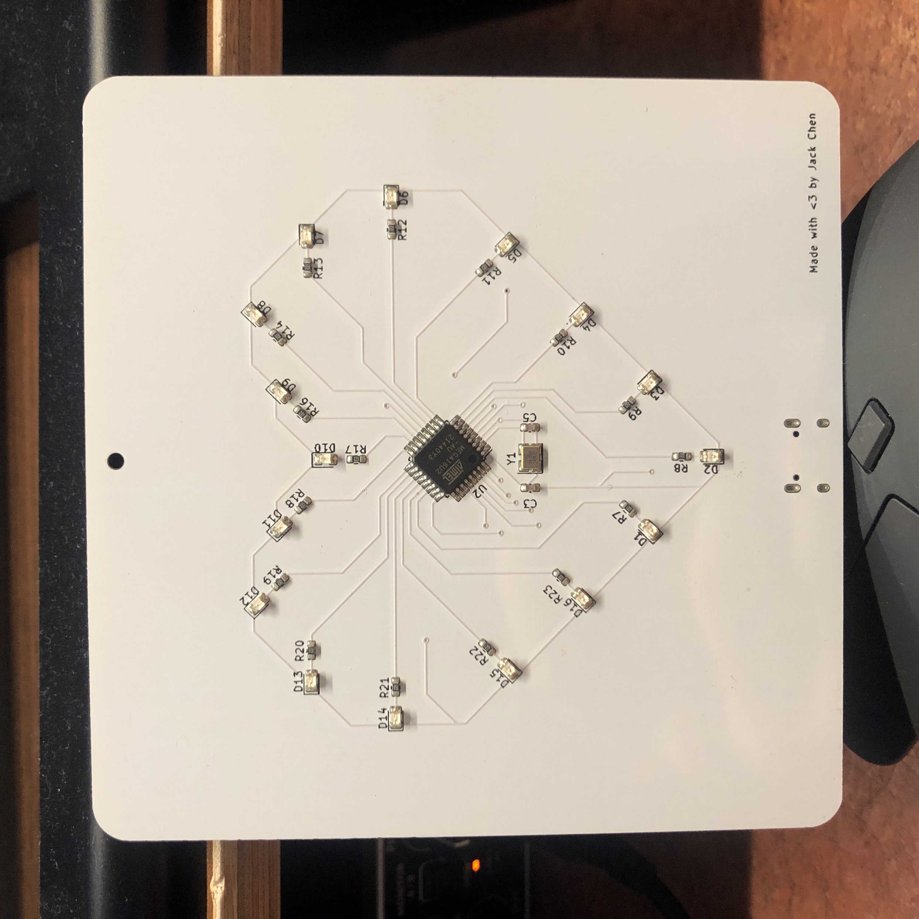
For reasons of aesthetic purity, everything visible on the front-side of the PCB must be part of the heart. No vias outside of the heart!
Added a small hole to the top of the PCB, so you could thread a string through it and hang the module on somewhere
The geometry of the heart took some time to get right, but it turned out ok.
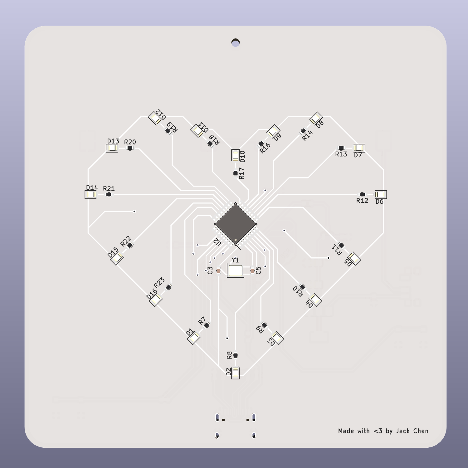
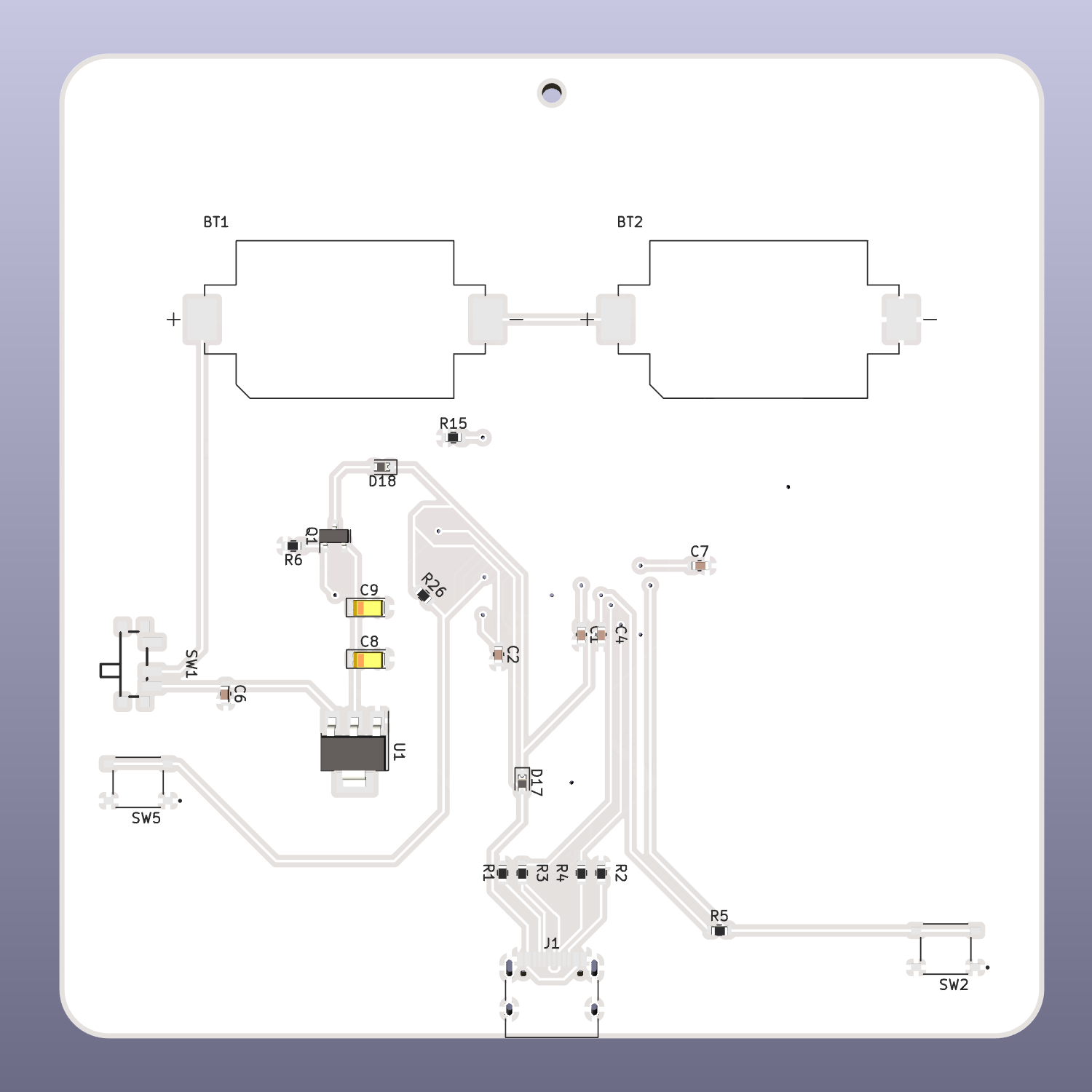
I exported the Gerber files and BOM, and sent it off to JLCPCB for manufacture. Here are some renders:
In my humble opinion, using Arduino as a university student in computer science is akin to intellectual cowardice. It is a sign that one lacks to bravery to face the almighty datasheet. /s
I programmed this in AVR C because I wanted to learn more about how microcontrollers worked at a lower level. Implementing I/O functions and interrupts by directly interacting with registers was a fun challenge and made the end result all the more rewarding.
The code is structured as such:
I have system of decoding arrays so that the corresponding bits at the corresponding registers for each LED can be easily accessed via an index, where 0 is the top LED and the index moves through the heart clockwise.
The program runs on an infinite loop, which relies on a frame counter that increments and resets periodically. For each lighting mode, I have done some rudimentary maths to map the frame counter to the indices of the LEDs that need to be turned on or off.
An interrupt service routine is defined such that whenever the push-button (connected to Pin C2) is pressed, the loop resets and and the lighting mode changes.
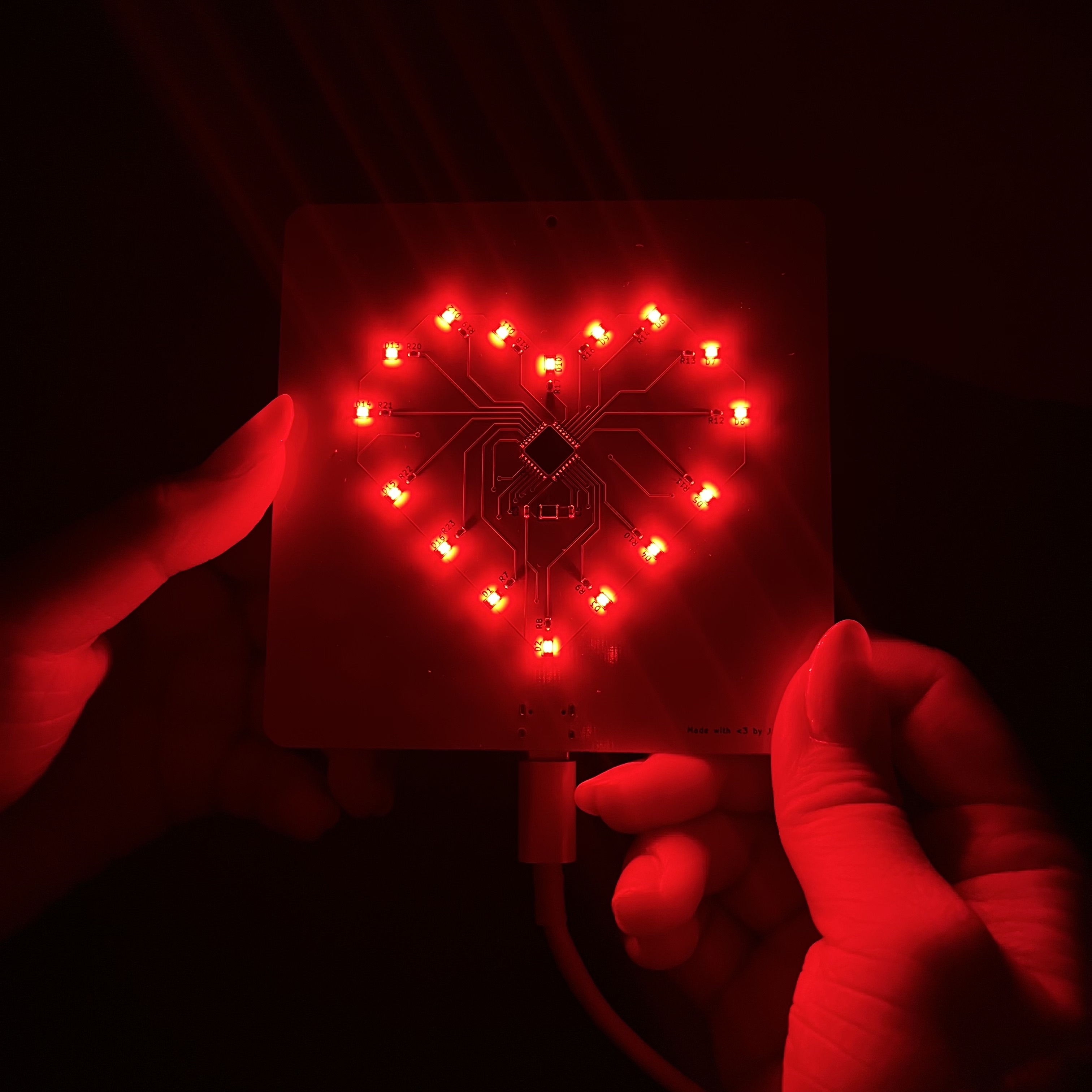
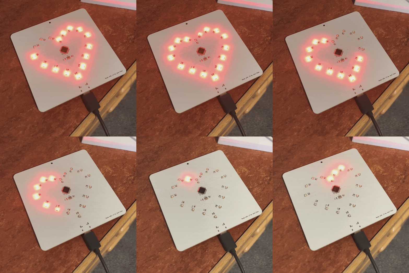
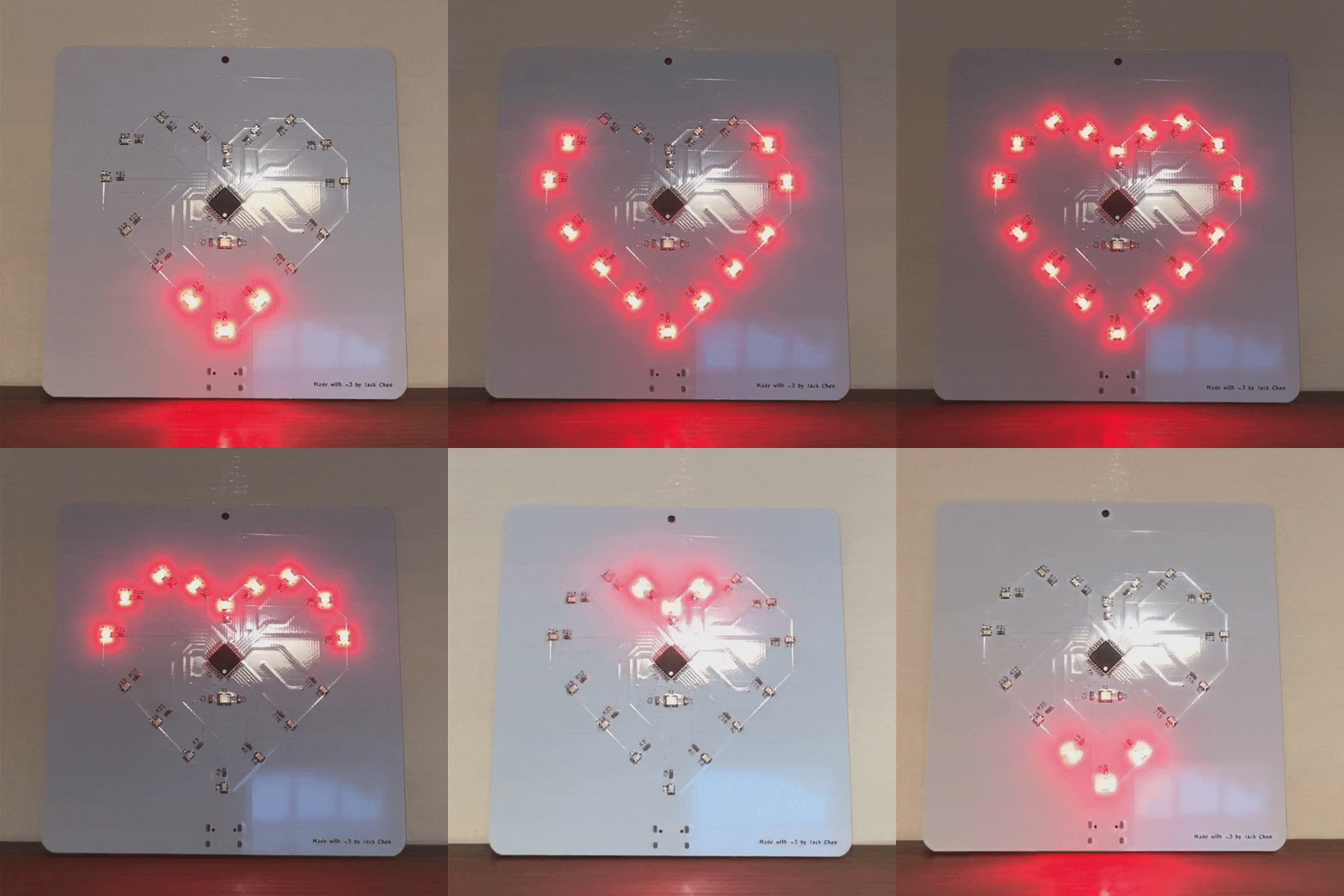
There are currently 5 lighting modes built into the program : twinkle, heartbeat, vertical sweep, snake, and solid (hopefully these names are all self-explanatory).
| Qty | Value | Footprint | References |
|---|---|---|---|
| 16 | 220 | Resistor_SMD:R_0603_1608Metric | R7, R8, R9, R10, R11, R12, R13, R14, R16, R17, R18, R19, R20, R21, R22, R23 |
| 16 | LED_Small | LED_SMD:LED_0805_2012Metric | D1, D2, D3, D4, D5, D6, D7, D8, D9, D10, D11, D12, D13, D14, D15, D16 |
| 3 | 10K | Resistor_SMD:R_0603_1608Metric | R5, R15, R26 |
| 2 | 0.1uF | Capacitor_SMD:C_0603_1608Metric | C1, C2 |
| 2 | 10uF | Capacitor_Tantalum_SMD:CP_EIA-3216-18_Kemet-A | C8, C9 |
| 2 | 22 | Resistor_SMD:R_0603_1608Metric | R3, R4 |
| 2 | 22pF | Capacitor_SMD:C_0603_1608Metric | C3, C5 |
| 2 | 5.1K | Resistor_SMD:R_0603_1608Metric | R1, R2 |
| 2 | CR2032 (3V) | Footprints:BAT_CR2032-BS-6-1 | BT1, BT2 |
| 2 | D_Schottky_Small | Diode_SMD:D_0603_1608Metric | D17, D18 |
| 2 | SW_Push | Footprints:SW_TS-1187A-B-A-B | SW2, SW5 |
| 1 | 100K | Resistor_SMD:R_0603_1608Metric | R6 |
| 1 | 10uF | Capacitor_SMD:C_0603_1608Metric | C6 |
| 1 | 1uF | Capacitor_SMD:C_0603_1608Metric | C7 |
| 1 | 4.7uF | Capacitor_SMD:C_0603_1608Metric | C4 |
| 1 | AMS1117-5.0 | Package_TO_SOT_SMD:SOT-223-3_TabPin2 | U1 |
| 1 | ATmega16U2-A | Package_QFP:TQFP-32_7x7mm_P0.8mm | U2 |
| 1 | Crystal_GND24 | Crystal:Crystal_SMD_3225-4Pin_3.2x2.5mm | Y1 |
| 1 | Q_PMOS_GSD | Package_TO_SOT_SMD:SOT-23 | Q1 |
| 1 | SW_SPDT | Footprints:SW-SMD_MK-12C02-G020 | SW1 |
| 1 | USB_C_Receptacle_USB2.0 | Connector_USB:USB_C_Receptacle_HRO_TYPE-C-31-M-12 | J1 |
It measures 100 × 100 mm and has 2 copper layers, 1.6 mm thick.
61 parts, built around the ATMEGA16U2-AU and AMS1117-5.0. The full list of its parts is on this page, with links to each part's symbol and footprint where PCBKit's library has them.
From the iamjackchen/SLLed repository on GitHub, at the commit this page was made from: the board is Hardware/ProjectSLL.kicad_pcb and its schematic Hardware/ProjectSLL.kicad_sch. PCBKit opens the board in the browser, with nothing to install.
Its repository states no licence, so its author keeps all rights: ask iamjackchen before reusing the design.


FlightDeckDIY/G1000-NXi-Mega
Welcome to the G1000 NXi Mega project! This repository contains the schematic and PCB design files for a custom-built G1000 avionics panel, designed specifically for use with flight simulators like Microsoft Flight…

PrinceOfPuppers/smart-home-server
A Full Smart Home System and Associated IOT Devices

daviddzekwer/Arduino-Uno-R3-PCB-Design
This project is a replica of the official Arduino Uno R3 designed using KiCad 10 as part of an Electrical and Electronics Engineering PCB Design assignment.

harichandanrajiv-lab/AG328X-REV-1
AG328X REV-1 is a compact, redesigned implementation of the Arduino UNO platform,. The project focuses on improving the original UNO architecture through a significantly reduced PCB footprint, enhanced power…
