
4 layers50 × 50 mm
The circuits for detecting licks were developed and built by M. Ghanbari (University of Cologne).
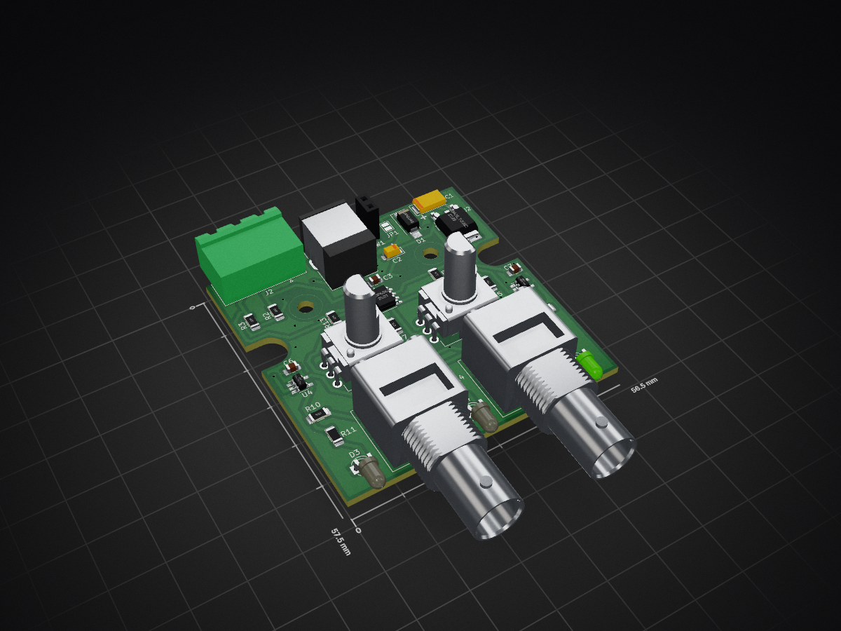
603-A is an open-source printed circuit board by iBehave-eLab, from the iBehave-eLab/Mouse-lick-detection repository on GitHub, published under the MIT licence. It is a 2-layer board of 56.5 × 57.5 mm with 36 parts on 22 nets, routed with 179 tracks and 26 vias.
It is built around the 74LVC1G125, MCP6562-E/SN and 10MQ040N. Its parts include 13 resistors, 5 capacitors, 4 ICs, 4 diodes and 4 connectors.


The circuits for detecting licks were developed and built by M. Ghanbari (University of Cologne).
Lick Detector circuits - "The board is equipped with a comparator based on operational amplifier technology. The mouse traverses the board, which is grounded. The inverted input is connected to the lick spout via a wire. Upon licking the spout, the internal resistance of the mouse pulls the inverted input to ground, raising the comparator output to +Vcc. The reference voltage is set to +Vcc/2 using a voltage divider.
In the normal state, when the mouse does not lick the spout, the output signal level is at zero. This implies that the inverted input is connected to +Vcc through a pull-up resistor, while the non-inverted input is set to +Vcc/2. The output voltage is at a logical zero level.


| Qty | Value | Footprint | References |
|---|---|---|---|
| 4 | 10k | Resistor_SMD:R_1206_3216Metric_Pad1.30x1.75mm_HandSolder | R4, R5, R6, R7 |
| 3 | 100n | Capacitor_SMD:C_0805_2012Metric_Pad1.18x1.45mm_HandSolder | C3, C6, C7 |
| 3 | LED | LED_THT:LED_D3.0mm | D2, D3, D4 |
| 2 | 1,6k | Resistor_SMD:R_1206_3216Metric_Pad1.30x1.75mm_HandSolder | R11, R14 |
| 2 | 10k | Potentiometer_THT:Potentiometer_Alps_RK09K_Single_Vertical | RV1, RV2 |
| 2 | 47M | Resistor_SMD:R_1206_3216Metric_Pad1.30x1.75mm_HandSolder | R2, R3 |
| 2 | 4M7 | Resistor_SMD:R_1206_3216Metric_Pad1.30x1.75mm_HandSolder | R12, R13 |
| 2 | 50R | Resistor_SMD:R_1206_3216Metric_Pad1.30x1.75mm_HandSolder | R10, R15 |
| 2 | 74LVC1G125 | Package_TO_SOT_SMD:SOT-23-5_HandSoldering | U3, U4 |
| 2 | Conn_Coaxial | Connector_Coaxial:BNC_Amphenol_B6252HB-NPP3G-50_Horizontal | J3, J4 |
| 2 | MountingHole | MountingHole:MountingHole_3.2mm_M3 | H2, H4 |
| 1 | 10MQ040 | Diode_SMD:D_SMA_Handsoldering | D1 |
| 1 | 10µ/10V | Capacitor_Tantalum_SMD:CP_EIA-3216-18_Kemet-A_Pad1.58x1.35mm_HandSolder | C2 |
| 1 | 10µ/25V | Capacitor_Tantalum_SMD:CP_EIA-6032-15_Kemet-U_Pad2.25x2.35mm_HandSolder | C1 |
| 1 | 3k3 | Resistor_SMD:R_1206_3216Metric_Pad1.30x1.75mm_HandSolder | R1 |
| 1 | Barrel_Jack | Connector_BarrelJack:BarrelJack_CUI_PJ-063AH_Horizontal | J1 |
| 1 | Conn_01x03 | Connector_Phoenix_MSTB:PhoenixContact_MSTBA_2,5_3-G-5,08_1x03_P5.08mm_Horizontal | J2 |
| 1 | Jumper_NO_Small | Jumper:SolderJumper-2_P1.3mm_Open_Pad1.0x1.5mm | JP1 |
| 1 | LM78M05_TO252 | Package_TO_SOT_SMD:TO-252-2 | U2 |
| 1 | MCP6562 | Package_SO:SOIC-8_3.9x4.9mm_P1.27mm | U1 |
| 1 | SW_SPST | Connector_PinSocket_2.54mm:PinSocket_1x02_P2.54mm_Vertical | SW1 |


variegated-coffee/open-lcc-board
Schematics and PCB files for the Open LCC hardware

ATmega8/kiterf
Release KiteRF is a SDR system with K210 & FPGA & ESP32 as its core controller, which make SDR more intelligent, portable and cheap.

It measures 56.5 × 57.5 mm and has 2 copper layers, 1.6 mm thick.
36 parts, built around the 74LVC1G125, MCP6562-E/SN and 10MQ040N. The full list of its parts is on this page, with links to each part's symbol and footprint where PCBKit's library has them.
From the iBehave-eLab/Mouse-lick-detection repository on GitHub, at the commit this page was made from: the board is Board/603-A.kicad_pcb and its schematic Board/603-A.kicad_sch. PCBKit opens the board in the browser, with nothing to install.
Its repository publishes it under the MIT licence: you may reuse it on that licence's terms (keep the author's notice, and for a copyleft licence share your changes alike).