
4 layers168.2 × 109.6 mm

KiCad 7.0.x にて設計
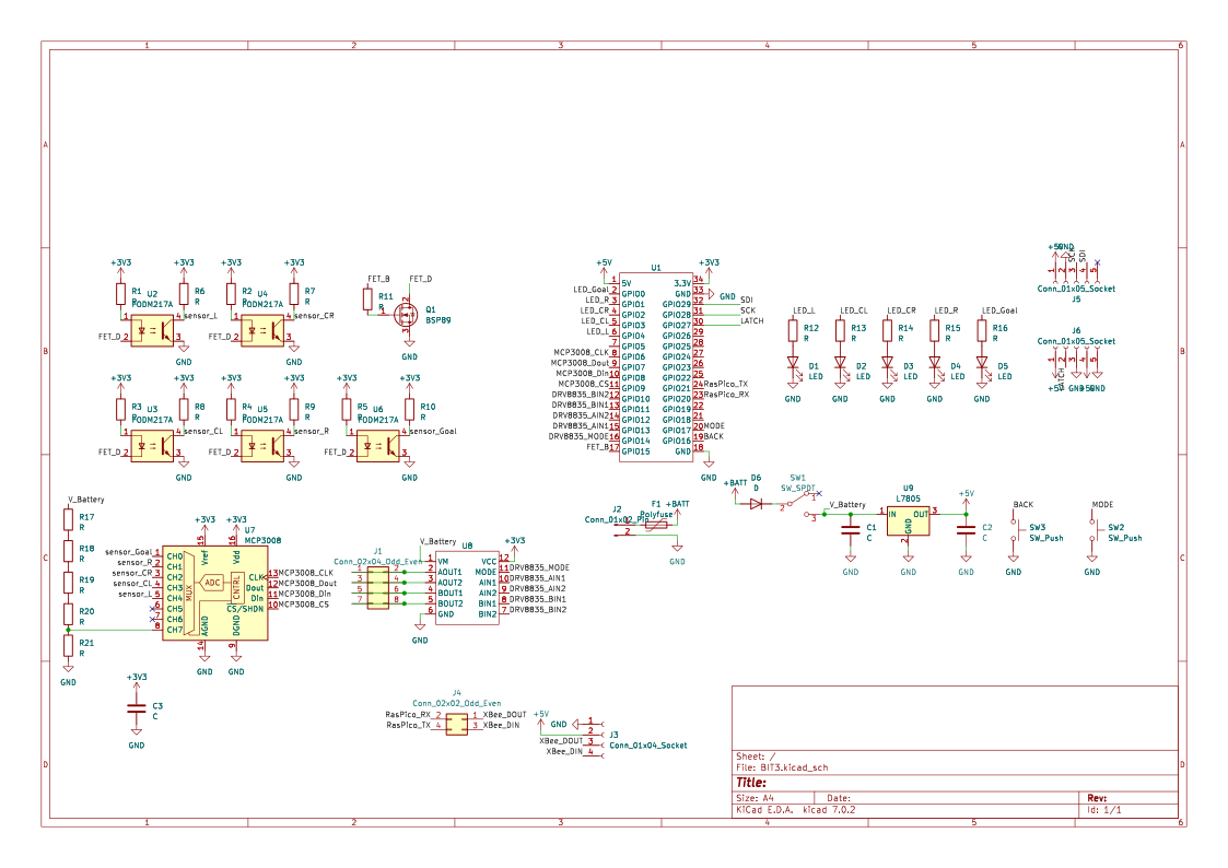
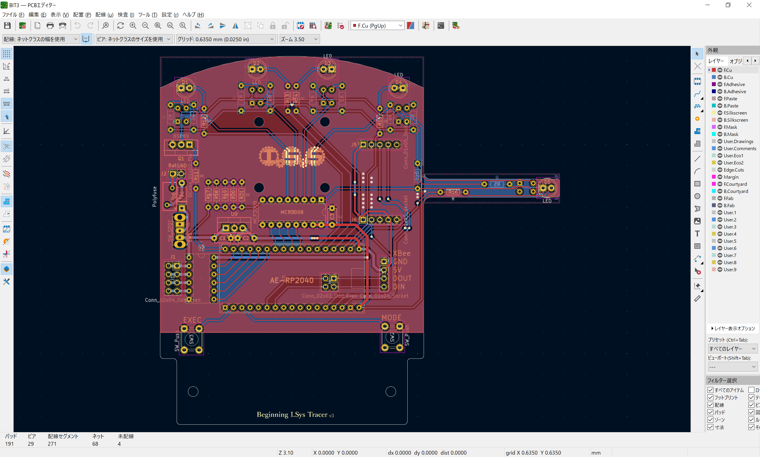
BIT3 is an open-source printed circuit board by I-Sys-UF, from the I-Sys-UF/BIT3_PCB repository on GitHub. It is a 2-layer board of 121.3 × 111.8 mm with 51 parts on 68 nets, routed with 271 tracks and 29 vias.
It is built around the MCP3008-I/P, FODM217A and L7805, with the BSP89 among its other parts. Its parts include 21 resistors, 9 ICs, 6 diodes, 6 connectors and 3 capacitors.


KiCad 7.0.x にて設計
Beginning I.Sys Tracer のイニシャルで、新入生教育用のライントレーサの筐体です
先代の BIT2 の設計を踏襲しつつ、マイコンを RP2040 搭載の秋月製 AE-RP2040 に置き換えました。ギアボックス等は流用できるようにしています
| 部品番号 | 部品名 | 秋月 |
|---|---|---|
| R1 - R5, R11 | 100 Ω | 125101 |
| R6 - R10 | 4.7k Ω | 125273 |
| R12 - R16 | 510 Ω | 125511 |
| R17 - R21 | 1k Ω | 125102 |
| C1 - C3 | 0.1 uF | 110147 |
| D1 - D5 | 5mm LED | 113172 |
| D6 | 1N4148 | 100941 |
| U1 | AE-RP2040 | 117542 |
| U2 - U6 | LBR-127HLD | 104500 |
| U7 | MCP3008 | 109485 |
| U7 | IC ソケット | 100007 |
| U8 | AE-DRV8835 | 109848 |
| U9 | NJM7805FA | 108678 |
| Q1 | MOSFET | 107597 |
| F1 | リセッタブルヒューズ | 112628 |
| SW1 | 電源スイッチ | 100300 |
| EXEC, MODE | タクタイルスイッチ | 103647 |
| J1 | 2 列ピンヘッダ | 100080 |
| J2 | バッテリ接続用ケーブル・コネクタ | 省略 |
| J3, U1 | 1 列ピンソケット | 105779 |
| J5, J6 | 7 セグメント LED | 110344 |
| 部品名 | 商品名 | リンク |
|---|---|---|
| 前輪 | タミヤ ボールキャスター | https://tamiyashop.jp/shop/g/g70144 |
| 動力 | タミヤ ダブルギヤボックス(左右独立4速タイプ) | https://tamiyashop.jp/shop/g/g70168 |
| 後輪 | タミヤ スリムタイヤセット | https://tamiyashop.jp/shop/g/g70193 |
| XBee | XBee S2C ワイヤアンテナ型 | https://www.switch-science.com/products/4089 |
| XBee 用変換基板 | XBeeエクスプローラ5Vマイコン用 | https://www.switch-science.com/products/1166 |
| XBee 用 USB アダプタ | XBeeエクスプローラUSBドングル | https://www.switch-science.com/products/1790 |
v1.0
v1.1
v1.2
v1.3
v1.4
v1.5
v1.6
v1.7
v2.0
v2.1
v2.2
V2.3

この 作品 は クリエイティブ・コモンズ 表示 - 非営利 - 改変禁止 4.0 国際 ライセンスの下に提供されています。
利用を希望される方は部の公式 Twitter までご連絡ください
| Qty | Value | Footprint | References |
|---|---|---|---|
| 21 | R | Resistor_THT:R_Axial_DIN0204_L3.6mm_D1.6mm_P7.62mm_Horizontal | R1, R2, R3, R4, R10, R11, R12, R13, R14, R15, R16, R17, R18, R19, R20, R21 +5 |
| 5 | FODM217A | AE-Parts:LBR-127HLD | U2, U3, U4, U5, U6 |
| 5 | LED | LED_THT:LED_D5.0mm | D1, D2, D3, D4, D5 |
| 3 | C | Capacitor_THT:C_Disc_D4.7mm_W2.5mm_P5.00mm | C1, C2, C3 |
| 2 | Conn_01x05_Socket | Connector_PinSocket_2.54mm:PinSocket_1x05_P2.54mm_Vertical | J5, J6 |
| 2 | SW_Push | Button_Switch_THT:SW_PUSH_6mm | SW2, SW3 |
| 1 | BSP89 | Package_TO_SOT_THT:TO-220-3_Vertical | Q1 |
| 1 | Conn_01x02_Pin | Connector_PinSocket_2.54mm:PinSocket_1x02_P2.54mm_Vertical | J2 |
| 1 | Conn_01x04_Socket | Connector_PinSocket_2.54mm:PinSocket_1x04_P2.54mm_Vertical | J3 |
| 1 | Conn_02x02_Odd_Even | Connector_PinSocket_2.54mm:PinSocket_2x02_P2.54mm_Vertical | J4 |
| 1 | Conn_02x04_Odd_Even | Connector_PinSocket_2.54mm:PinSocket_2x04_P2.54mm_Vertical | J1 |
| 1 | D | Diode_THT:D_A-405_P7.62mm_Horizontal | D6 |
| 1 | L7805 | Package_TO_SOT_THT:TO-220-3_Vertical | U9 |
| 1 | LOGO | LOGO | G*** |
| 1 | MCP3008 | Package_DIP:DIP-16_W7.62mm | U7 |
| 1 | Polyfuse | Fuse:Fuse_BelFuse_0ZRE0005FF_L8.3mm_W3.8mm | F1 |
| 1 | SW_SPDT | Button_Switch_THT:SW_Slide_1P2T_CK_OS102011MS2Q | SW1 |
| 1 | ~ | AE-Compornents:AE-RP2040 | U1 |
| 1 | ~ | AE-Compornents:AE-DRV8835 | U8 |
It measures 121.3 × 111.8 mm and has 2 copper layers, 1.6 mm thick.
51 parts, built around the MCP3008-I/P, FODM217A, L7805 and BSP89. The full list of its parts is on this page, with links to each part's symbol and footprint where PCBKit's library has them.
From the I-Sys-UF/BIT3_PCB repository on GitHub, at the commit this page was made from: the board is BIT3.kicad_pcb and its schematic BIT3.kicad_sch. PCBKit opens the board in the browser, with nothing to install.
Its repository states no licence, so its author keeps all rights: ask I-Sys-UF before reusing the design.

owntech-foundation/OWNVERTER
The OwnVerter is an open-source 3-phase power converter that can be used to control multiple types of motors and is compatible with different types of sensors.

RocketryVT/active-drag-system
Eigen Library, cmake, and arm-none-eabi-gcc tooling required for successful build.

openlab-aux/airlock
This repository contains various soft- and hardware sources for the OpenLab Augsburg Airlock.

cookiemonsternz/Eurorack-DIST
Every circuit has a gain, tone, and volume control, as well as a switch deciding whether to take input from the previous section or from the input jack.


gregoryy01/potatoesc
This repo contains greg's attempt to make a bldc controller for Semar Urban, please be nice
