8 layers22.3 × 77.5 mm
Tinker mantis
Tinkerbug-Robotics/TinkerRocket
Model rocket flight computer, ground station, iOS app, and simulation
279 parts1GPL-3.0

 i-Saac-IV/micro-affirmations
A microcontroller-based affection-giving MACHINE!
Micro affirmations is an open-source printed circuit board by i-Saac-IV, from the i-Saac-IV/micro-affirmations repository on GitHub, published under the MIT licence. It is a 2-layer board of 70 × 40 mm with 167 parts on 87 nets, routed with 369 tracks and 158 vias.
It is built around the TPS61094DSS and LDK130M-R. Its parts include 102 diodes, 28 resistors, 12 capacitors, 10 transistors and 3 ICs. It belongs with the lEDs and displays boards and the STM32 boards of this library.


A microcontroller-based affection-giving MACHINE!
[!IMPORTANT] This project is currently a work-in-progress, there will be things that don't work, please bear with me will I work out the kinks!
The PCB files can be found here, be sure of order a solder stencil too(ideally with a stencil unless you love hand-soldering 200+ SMD connections). The BOM will provide you with a list of parts required and their placements. Due to the limited size on the PCB, many of the reference designators have been removed to save space. Because of this, you will likely need to have KiCAD or the iBOM running as you are placing components. Or you can guess I suppose...
You will need access to an ST-Link programming device and have stm32-for-vscode extension installed. Once you're ready, upload the code by:
This device allows the user to create their own custom messages to be displayed on the LED matrix, to provide your messages, modify the following code found in this file.
For axample:
__weak const char *messages[] = {
    "This is the first custom message!",
    "Below is a list of supported characters...",
    "!\"#$%&'()*+,-./0123456789:;<=>?@ABCDEFGHIJKLMNOPQRSTUVWXYZ[\\]^_`abcdefghijklmnopqrstuvwxyz{|}~"
};
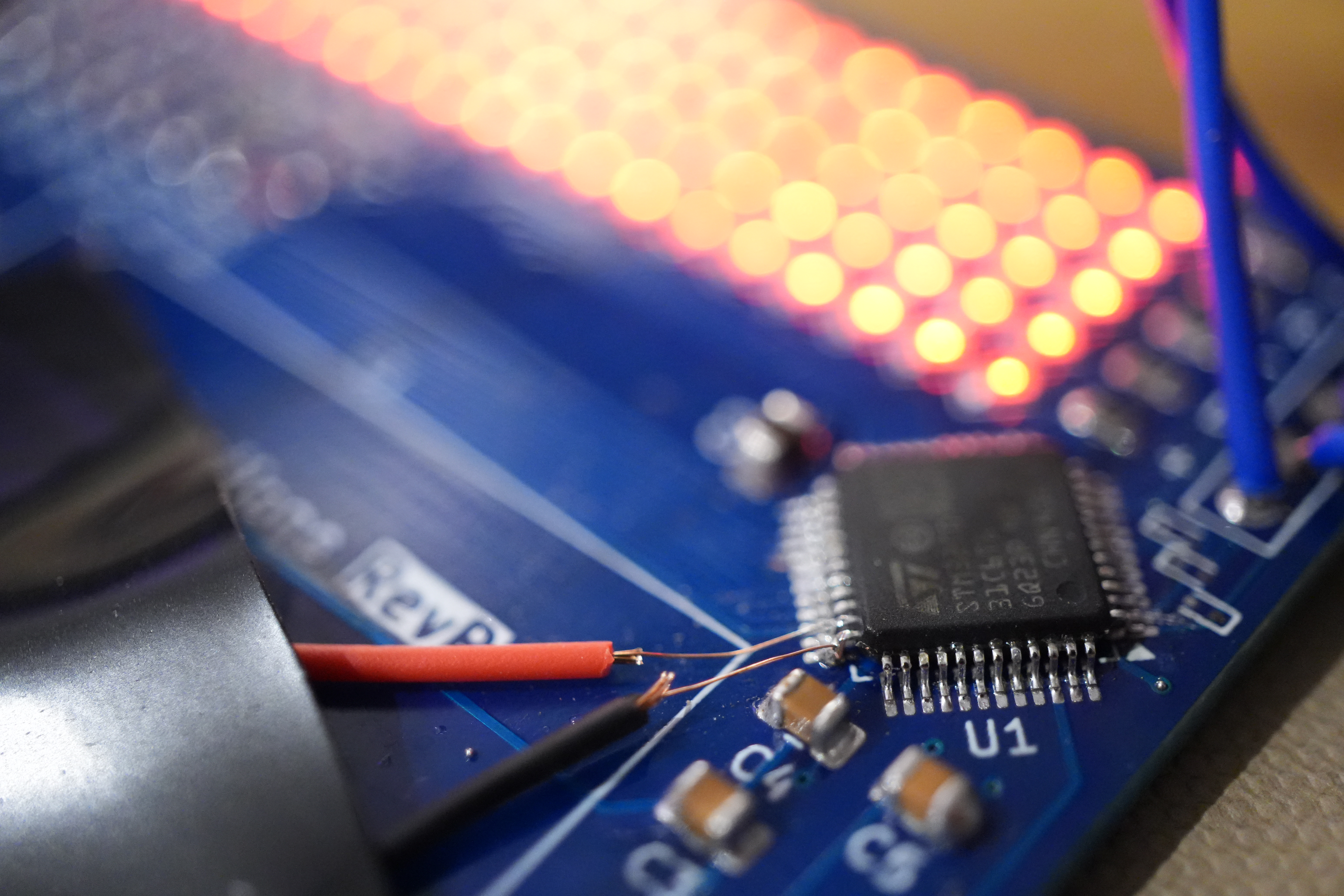 Programming port broken in RevB of the PCB |
After considerable development to the code, I found out that I had not connected the supercapacitor voltage sensing circuit to a ADC capable pin, this has been corrected. I also found that if the input voltage of the charging IC is greater than the output voltage = 100mV the bucking function of the IC is bypassed (meaning if the input is 5V the output is also 5V, bad for the STM chip), this has been fixed with the linear regulator.
After futher testing the following fixes to the hardware design have been made:
After hardware tesing the following fixes have been made to the hardware design:
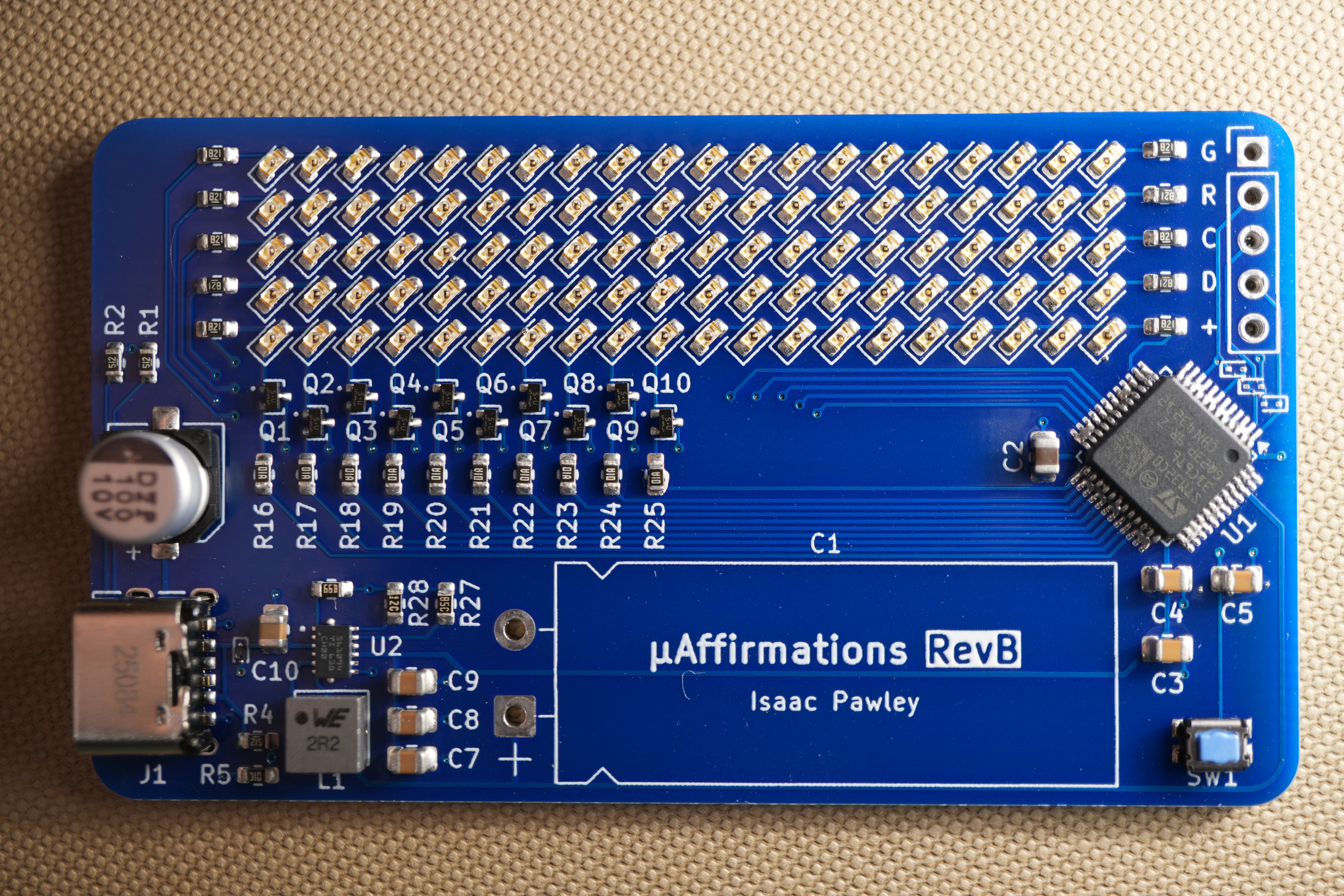 RevB PCB |
Initial hardware design.
See licence for in depth info.
If you'd like to get in touch, feel free to reach out!



| Qty | Value | Footprint | References |
|---|---|---|---|
| 100 | LED | Diode_SMD:D_0603_1608Metric | D10, D11, D12, D13, D14, D15, D16, D17, D18, D19, D20, D100, D101, D102, D103, D104 +84 |
| 10 | 100 | Resistor_SMD:R_0603_1608Metric | R16, R17, R18, R19, R20, R21, R22, R23, R24, R25 |
| 10 | 820 | Resistor_SMD:R_0603_1608Metric | R6, R7, R8, R9, R10, R11, R12, R13, R14, R15 |
| 10 | NCH | Package_TO_SOT_SMD:SOT-416 | Q1, Q2, Q3, Q4, Q5, Q6, Q7, Q8, Q9, Q10 |
| 7 | TestPoint | TestPoint:TestPoint_Pad_D1.0mm | TP2, TP3, TP4, TP5, TP6, TP7, TP8 |
| 4 | 10u | Capacitor_SMD:C_0805_2012Metric | C7, C8, C9, C10 |
| 3 | 100n | Capacitor_SMD:C_0805_2012Metric | C3, C4, C5 |
| 2 | 1u | Capacitor_SMD:C_0603_1608Metric | C11, C12 |
| 2 | 5.1k | Resistor_SMD:R_0603_1608Metric | R1, R2 |
| 1 | 1.5k | Resistor_SMD:R_0603_1608Metric | R3 |
| 1 | 100u | Capacitor_SMD:CP_Elec_6.3x5.4_Nichicon | C6 |
| 1 | 10k | Resistor_SMD:R_0603_1608Metric | R30 |
| 1 | 13.0k* | Resistor_SMD:R_0603_1608Metric | R28 |
| 1 | 15F | micro-affirmations_footprints:CP_Radial_L32.0mm_D12.5mm_P5.00mm_Horizontal | C1 |
| 1 | 2.2u | micro-affirmations_footprints:L_1616_4040Metric | L1 |
| 1 | 33k* | Resistor_SMD:R_0603_1608Metric | R29 |
| 1 | 4.75k | Resistor_SMD:R_0603_1608Metric | R26 |
| 1 | 4.7u | Capacitor_SMD:C_0805_2012Metric | C2 |
| 1 | 75.0k | Resistor_SMD:R_0603_1608Metric | R27 |
| 1 | CHARGE | Diode_SMD:D_0603_1608Metric | D1 |
| 1 | DEBUG | Connector_PinHeader_2.54mm:PinHeader_1x05_P2.54mm_Vertical | J2 |
| 1 | LDK130 | Package_TO_SOT_SMD:SOT-23-5 | U3 |
| 1 | MountingHole | MountingHole:MountingHole_2.2mm_M2 | H1 |
| 1 | RST | micro-affirmations_footprints:TL1030_A | SW1 |
| 1 | STM32C031C6Tx | Package_QFP:LQFP-48_7x7mm_P0.5mm | U1 |
| 1 | TPS61094 | micro-affirmations_footprints:WSON_94DSSR_TEX | U2 |
| 1 | USB-C | micro-affirmations_footprints:2171750001_MOL | J1 |
| 1 | ~ | Package_TO_SOT_SMD:SOT-23 | D2 |
Tinkerbug-Robotics/TinkerRocket
Model rocket flight computer, ground station, iOS app, and simulation


Ardumower/ardumower
Develop an open source robotic lawn mower (HW+SW reference platform)

polykit/polykit-x-monosynth
The Polykit X1 is a DIY semi-modular, analog, patchable synthesizer

byungyoonc/TrueStrike42
TrueStrike42 is a columnar staggered unibody split keyboard designed to maximize performance and minimize finger fatigue.


barisdinc/N3B_SDR_Transceiver_HW
V/U/SHF and QO-100 SDR Transceiver Project

It measures 70 × 40 mm and has 2 copper layers, 1.6 mm thick.
167 parts, built around the TPS61094DSS and LDK130M-R. The full list of its parts is on this page, with links to each part's symbol and footprint where PCBKit's library has them.
From the i-Saac-IV/micro-affirmations repository on GitHub, at the commit this page was made from: the board is hw/pcb/micro-affirmations.kicad_pcb and its schematic hw/pcb/led-matrix.kicad_sch. PCBKit opens the board in the browser, with nothing to install.
Its repository publishes it under the MIT licence: you may reuse it on that licence's terms (keep the author's notice, and for a copyleft licence share your changes alike).