2 layers101.6 × 53.3 mm
Carte Son Arduino Mega
hwreverse/CoursPCBDesign
Sources pour les séquences de cours sur Twitch/Youtube (Alexx_and_seb) sur le PCB Design
35 partsCC0-1.0
 hwreverse/CoursPCBDesign
Sources pour les séquences de cours sur Twitch/Youtube (Alexx_and_seb) sur le PCB Design
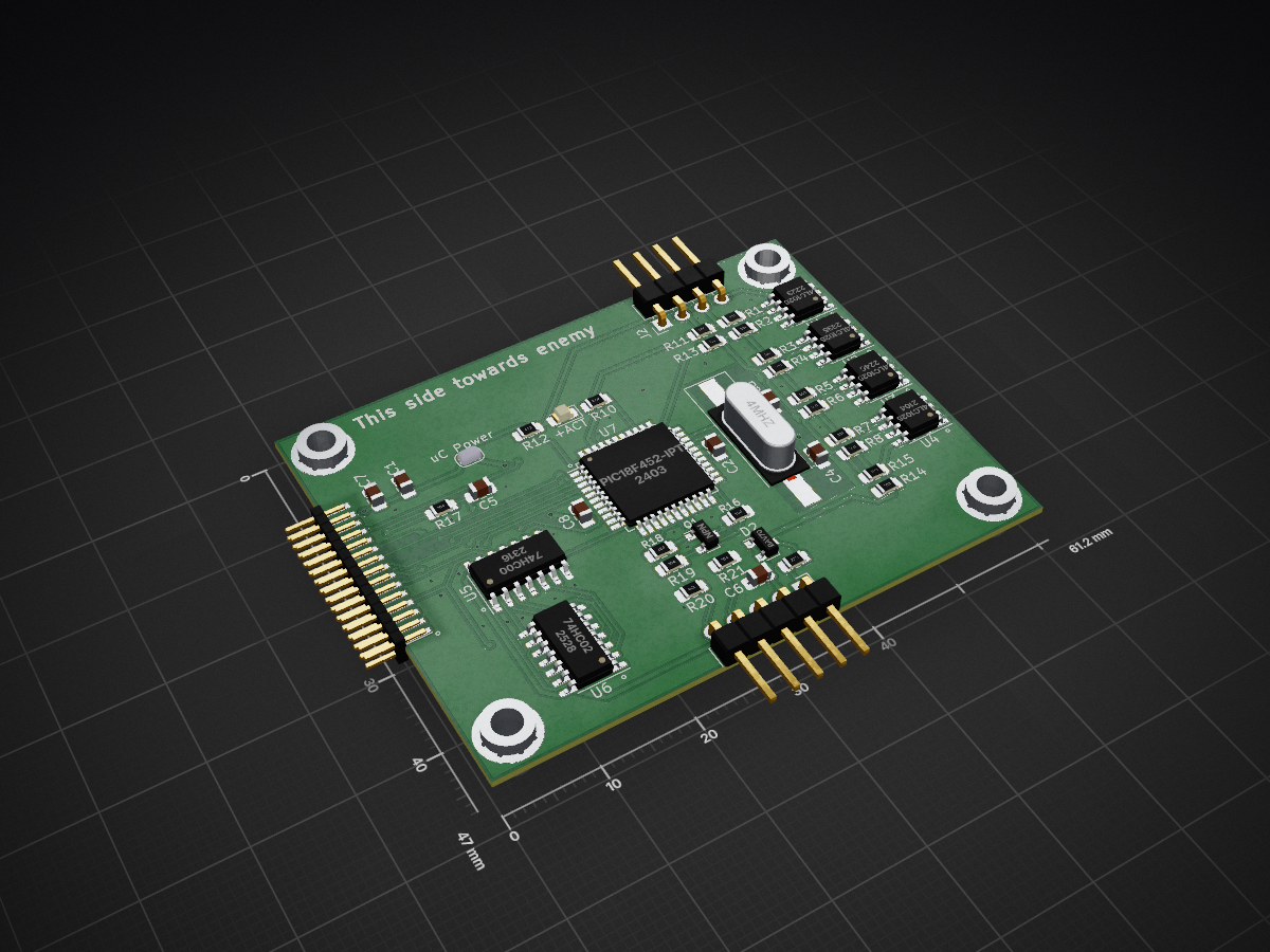
MD-100 Emulator is an open-source printed circuit board by hwreverse, from the hwreverse/CoursPCBDesign repository on GitHub, published under the CC0-1.0 licence. It is a 2-layer board of 61.2 × 47 mm with 48 parts on 53 nets, routed with 438 tracks and 72 vias.
It is built around the 24LC1025-I/P, 74HC00D and 74HC02, with the BAV70 among its other parts. Its parts include 21 resistors, 8 capacitors, 7 ICs, 3 connectors and 2 diodes. It belongs with the PIC boards of this library.


Sources pour les séquences de cours sur Twitch/Youtube (Alexx_and_seb) sur le PCB Design
| Qty | Value | Footprint | References |
|---|---|---|---|
| 10 | 330R | Resistor_SMD:R_0805_2012Metric_Pad1.15x1.40mm_HandSolder | R1, R2, R3, R4, R5, R6, R7, R8, R11, R13 |
| 4 | 100K | Resistor_SMD:R_0805_2012Metric_Pad1.15x1.40mm_HandSolder | R16, R17, R19, R20 |
| 4 | 15pF | Capacitor_SMD:C_0805_2012Metric_Pad1.15x1.40mm_HandSolder | C3, C4, C5, C6 |
| 4 | 24LC1025 | Package_SO:SOIC-8_3.9x4.9mm_P1.27mm | U1, U2, U3, U4 |
| 4 | MountingHole_Pad | MountingHole:MountingHole_3.2mm_M3_Pad_Via | H1, H2, H3, H4 |
| 3 | 0.1uF | Capacitor_SMD:C_0805_2012Metric_Pad1.15x1.40mm_HandSolder | C2, C7, C8 |
| 2 | 10K | Resistor_SMD:R_0805_2012Metric_Pad1.15x1.40mm_HandSolder | R14, R15 |
| 1 | 100k | Resistor_SMD:R_0805_2012Metric_Pad1.15x1.40mm_HandSolder | R21 |
| 1 | 10uF | Capacitor_SMD:C_0805_2012Metric_Pad1.15x1.40mm_HandSolder | C1 |
| 1 | 220K | Resistor_SMD:R_0805_2012Metric_Pad1.15x1.40mm_HandSolder | R18 |
| 1 | 22K | Resistor_SMD:R_0805_2012Metric_Pad1.15x1.40mm_HandSolder | R9 |
| 1 | 47K | Resistor_SMD:R_0805_2012Metric_Pad1.15x1.40mm_HandSolder | R12 |
| 1 | 4K7 | Resistor_SMD:R_0805_2012Metric_Pad1.15x1.40mm_HandSolder | R10 |
| 1 | 4MHz | Crystal:Crystal_SMD_HC49-SD_HandSoldering | Y1 |
| 1 | 74HC00 | Package_SO:SOIC-14_3.9x8.7mm_P1.27mm | U5 |
| 1 | 74HC02 | Package_SO:SOIC-14_3.9x8.7mm_P1.27mm | U6 |
| 1 | BAV70 | Package_TO_SOT_SMD:SOT-23 | D2 |
| 1 | CPB_Connector | hwreverse:Connector_Casio_2x15_1.27_SYSBUS | J1 |
| 1 | GRN | LED_SMD:LED_0805_2012Metric_Pad1.15x1.40mm_HandSolder | D1 |
| 1 | I2CConn | Connector_PinHeader_2.54mm:PinHeader_1x04_P2.54mm_Horizontal | J2 |
| 1 | ICSP | Connector_PinHeader_2.54mm:PinHeader_1x05_P2.54mm_Horizontal | J3 |
| 1 | JVCC | Jumper:SolderJumper-2_P1.3mm_Open_RoundedPad1.0x1.5mm | JP1 |
| 1 | NPN | Package_TO_SOT_SMD:SOT-23 | Q1 |
| 1 | PIC18F452-IPT | Package_QFP:TQFP-44_10x10mm_P0.8mm | U7 |
hwreverse/CoursPCBDesign
Sources pour les séquences de cours sur Twitch/Youtube (Alexx_and_seb) sur le PCB Design

hwreverse/CoursPCBDesign
Sources pour les séquences de cours sur Twitch/Youtube (Alexx_and_seb) sur le PCB Design

hwreverse/CoursPCBDesign
Sources pour les séquences de cours sur Twitch/Youtube (Alexx_and_seb) sur le PCB Design

felipesantiagoach-ops/cdp1802-8bit-computer
8-bit microcomputer based on the RCA CDP1802, the first CMOS microprocessor. Three stages designed in KiCad: two built and tested (assembly programs, UART, Tiny BASIC, Elf/OS) and a final design with an ADC, I²C/SPI…

slu4coder/Minimal-64x4-Home-Computer
My DIY TTL home computer with VGA and PS/2 and 4x the processing power of a Commodore C64 or Apple II.

slu4coder/Minimal-UART-Computer-1-2
Legacy: Version 1 and 2 of my TTL-only CPU featuring UART I/O, an expansion port, 512KB SSD at up to 10MHz clock speed


It measures 61.2 × 47 mm and has 2 copper layers, 0.8 mm thick.
48 parts, built around the 24LC1025-I/P, 74HC00D, 74HC02 and BAV70. The full list of its parts is on this page, with links to each part's symbol and footprint where PCBKit's library has them.
From the hwreverse/CoursPCBDesign repository on GitHub, at the commit this page was made from: the board is MD-100 Emulator/MD-100 Emulator.kicad_pcb. PCBKit opens the board in the browser, with nothing to install.
Its repository publishes it under the CC0-1.0 licence: you may reuse it on that licence's terms (keep the author's notice, and for a copyleft licence share your changes alike).