
4 layers137 × 86 mm

 hustav/amstrad_isa
Amstrad PPC ISA Extension Board
Ppc isa expansion is an open-source printed circuit board by hustav, from the hustav/amstrad_isa repository on GitHub, published under the MIT licence. It is a 2-layer board of 113.4 × 87.9 mm with 22 parts on 80 nets, routed with 1,413 tracks and 130 vias.
It is built around the 74HC244D. Its parts include 8 capacitors, 5 connectors, 2 ICs, 1 resistor and 1 diode.
An open-hardware KiCad 8 design for an external-mount, internally-powered 3-slot XT-class (8-bit) ISA expansion board for the Amstrad PPC 512 and PPC 640 portable PCs.
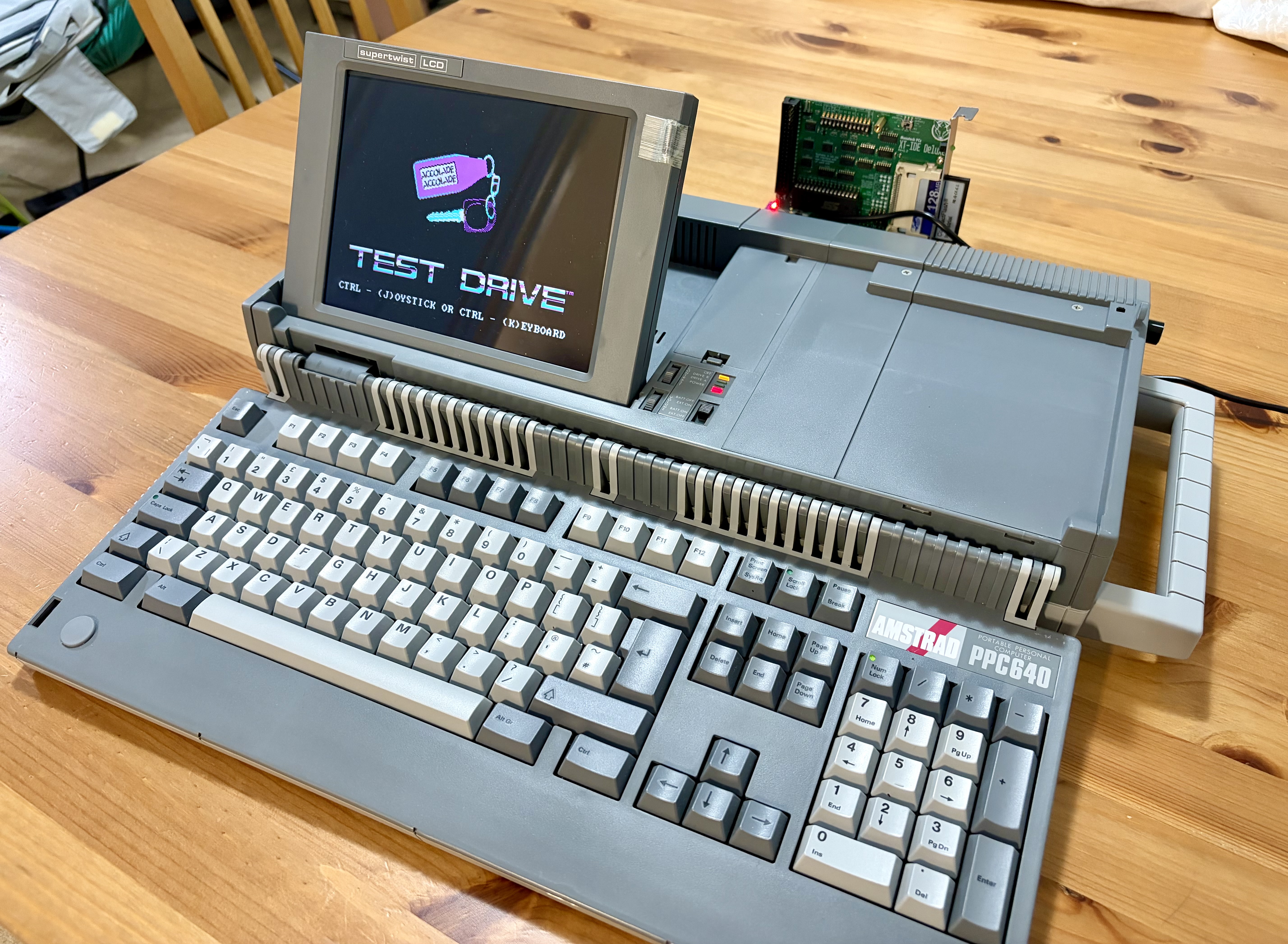
The PPC is the 1988-era Amstrad luggable that ships with a CMOS-level expansion connector (DB25 + DB37) on its back. Amstrad sold an external "Expansion Box" that was meant to power the PPC and add peripheral slots. This project inverts the original topology: it takes power from the PPC's own PSU and gives you three standard XT 8-bit ISA slots in a compact board that clips onto the back of the machine via the two DB connectors — ready to host modern flash-based peripherals (XT-IDE, floppy emulators, network cards, etc.).
The board has been fabricated and tested in a real Amstrad PPC 640 — booting DOS from a CompactFlash card via an XT-IDE controller. Photos below are of the assembled board in service.
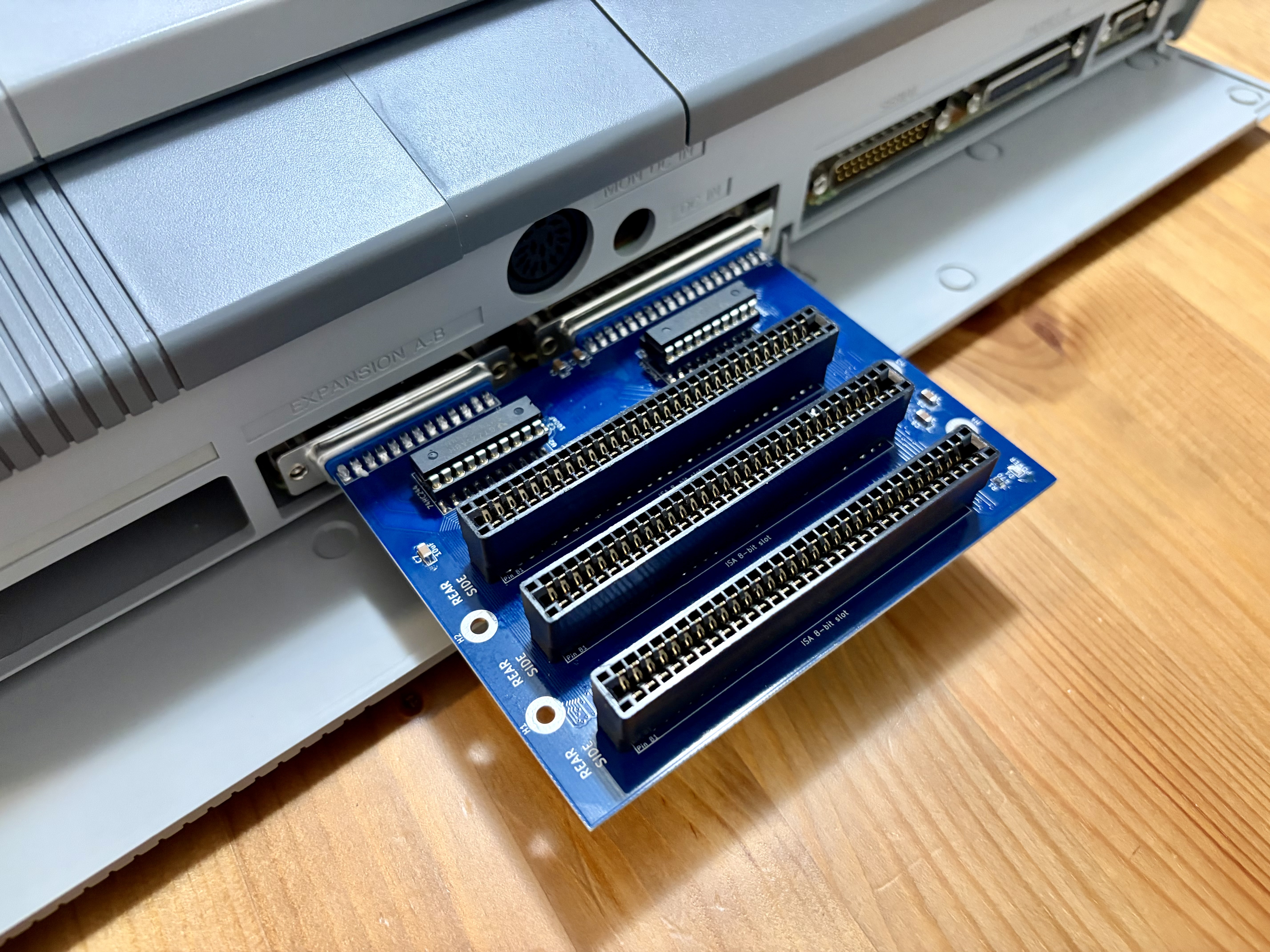 | 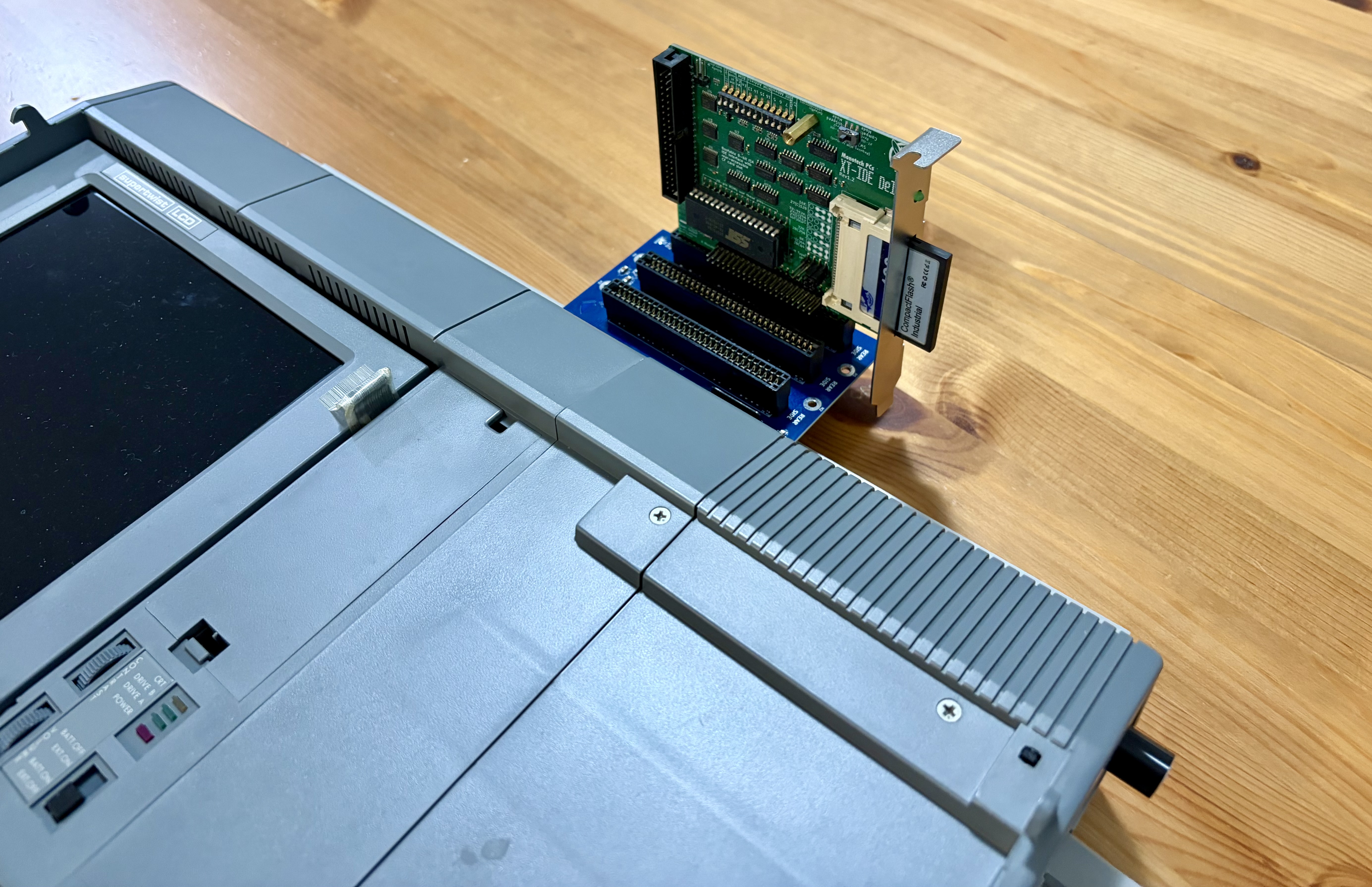 |
| Board mated to the PPC's DB25 + DB37 expansion port. | Top-down view showing the three ISA slots fanning out the back. |
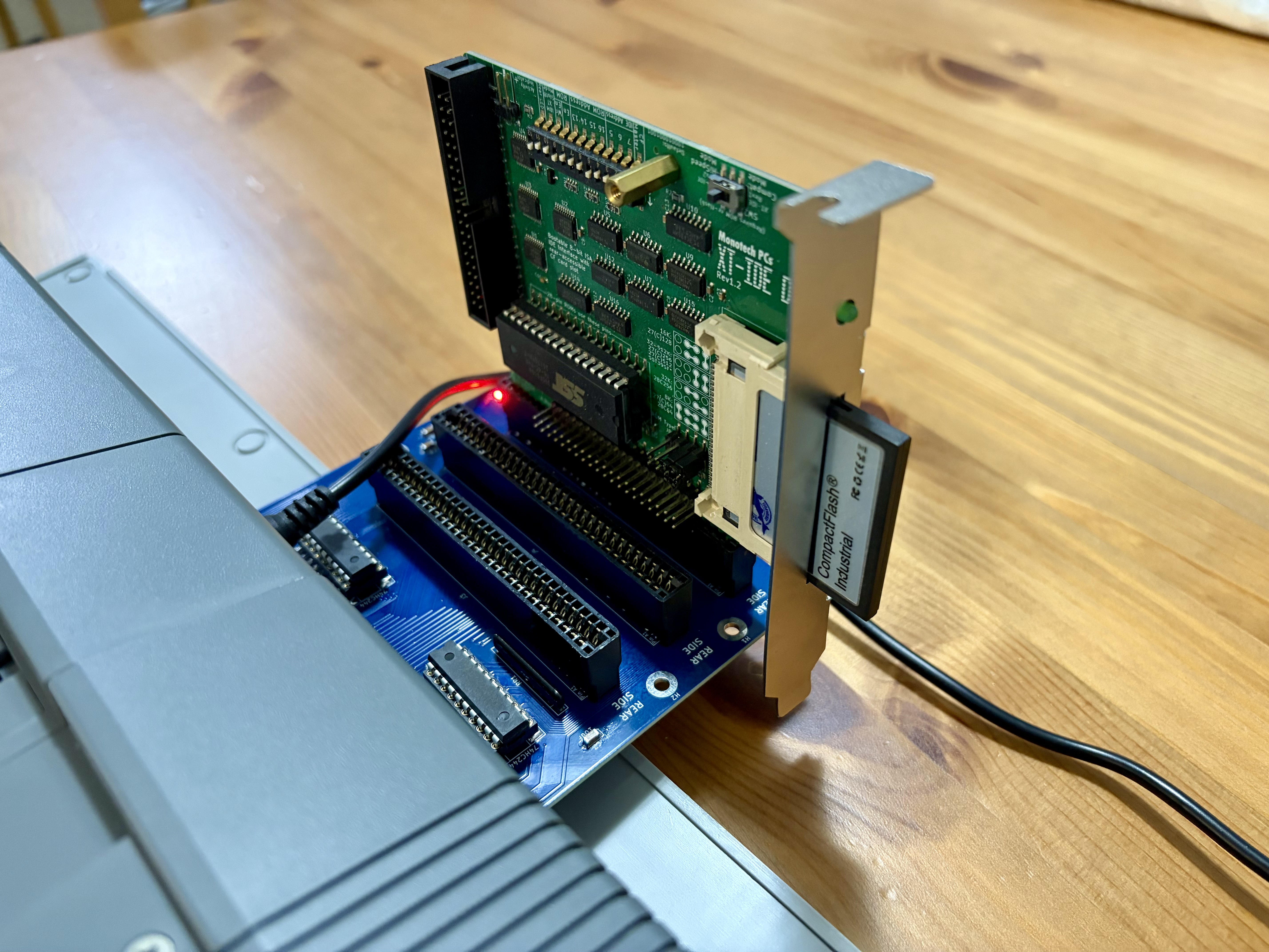 | |
| XT-IDE card with CompactFlash plugged into the centre slot. | The PPC 640 booting and running Test Drive from the CF card. |
amstrad_isa/
├── README.md                  — this file
├── LICENSE                    — MIT
├── .gitignore                 — KiCad / Python / OS cruft
├── kicad/
│   ├── ppc-isa-expansion.kicad_pro
│   ├── ppc-isa-expansion.kicad_sch
│   ├── ppc-isa-expansion.kicad_pcb
│   ├── sym-lib-table          — project-local symbol libraries
│   ├── fp-lib-table           — project-local footprint libraries
│   └── ppc-isa.pretty/        — custom ISA 8-bit slot footprint
├── scripts/
│   ├── generate_schematic.py  — regenerates the schematic from tables
│   ├── generate_pcb.py        — regenerates the PCB skeleton
│   └── generate_bom.py        — emits docs/BOM.csv
├── fab/                       — ready-to-order gerbers + JLCPCB zip
├── docs/
│   ├── design_notes.md        — the *why* behind the schematic choices
│   ├── BOM.csv                — bill of materials
│   └── Amstrad_PPC_Technical_Reference_Manual.pdf
└── photos/ — build & in-machine reference shotsIf you don't want to install KiCad, the fab/ folder contains a
ready-to-order gerber set straight from the committed .kicad_pcb.
fab/ppc-isa-expansion-gerbers.zip
(no need to extract it).docs/BOM.csv.The gerbers in fab/ always match the committed .kicad_pcb. If you fork
and re-route, re-plot from KiCad and replace the contents of fab/.
git clone git@github.com:hustav/amstrad_isa.git
cd amstrad_isa

# Optional: regenerate the schematic / PCB from the Python source of truth
python3 scripts/generate_schematic.py
python3 scripts/generate_pcb.py

# Open the project
kicad kicad/ppc-isa-expansion.kicad_pro
The .kicad_sch and .kicad_pcb files were initially generated by the
scripts in scripts/ — those scripts remain the source of truth for the
netlist. The current .kicad_pcb has been routed by hand on top of that
skeleton, so re-running generate_pcb.py would overwrite the routing.
If you need to change the netlist, regenerate the skeleton and then redo
the affected traces.
| Area | Choice | Reason |
|---|---|---|
| Form factor | External-mount, ~120 × 99 mm | Clips onto the PPC's DB25 + DB37 expansion port |
| Slots | 3 × XT 8-bit ISA (62-pin) | Standard pinout, matches prior-art boards |
| Power source | Drawn from the PPC's internal PSU via the expansion cable | No external brick required |
| −5 V rail | Taken directly from connector B pin 17 | Tech Ref §1.18 confirms PPC sources −5 V |
| Component style | SMD only — SOIC, 0805, SIP network | Hand-solderable with a fine-tip iron |
| Buffering | 2 × 74HC244 for A00..A07 + 8 control signals | Drives the loaded capacitance of 3 ISA slots |
| Data bus | Unbuffered, 10 kΩ pull-ups via RR1 | Per Amstrad Tech Ref CMOS-to-TTL note |
| Activity LED | Removed (BEAT flip-flop omitted) | Purely cosmetic; saves 1× SOIC-14 + RC bits |
Full rationale lives in docs/design_notes.md.
The Amstrad PPC Technical Reference Manual (§1.18) states that the original Expansion Box is intended to supply power to the PPC, not draw from it. Connector B pin 20 is an EXT PWR input to the PPC's regulator.
This design reverses that flow — all four rails (+5 V, +12 V, −5 V, −12 V) are drawn from the PPC's expansion connector:
Pin 20 (EXT PWR into the PPC) is left floating — voltage is never injected back into the PPC.
Safe for modern peripherals. An original floppy or 10 MB Winchester drew 5–10 W. A flash-based XT-IDE with a CF card draws ~100–200 mA on +5 V (0.5–1 W). Three flash peripherals are comfortably within the headroom the original PSU left for the Expansion Box port.
Not safe for original drives. If you try to use the original floppy or HDD controllers through this board, the PPC's PSU may brown out. In that case, build an externally-powered (ATX) variant instead.
Mostly the address bus.
| Pin | Signal | Notes |
|---|---|---|
| 1 | +5 V | power input |
| 2 | TC | DMA terminal-count |
| 3, 16, 4, 17, 5, 18, 6, 19, 7, 20, 8, 21 | A19..A08 | Unbuffered |
| 9, 22, 10, 23, 11, 24, 12, 25 | A07b..A00b | Buffered on PPC side; re-buffered by U2 |
| 13 | AEN | Address enable |
| 14 | GND | |
| 15 | DACK0 |
Data bus, IRQs, DMA, control signals, power.
| Pin | Signal | Notes |
|---|---|---|
| 1 | −20 V | unused, left NC |
| 2–4, 21–23 | IRQ2..IRQ7 | Pass-through |
| 5 | I/O RDY | Pass-through |
| 6, 24–25 | DACK1..DACK3 | Pass-through |
| 7 | I/O CHCK | Pass-through |
| 8, 26–27 | DRQ1..DRQ3 | Pass-through |
| 9 | OSC(b) | 14.318 MHz buffered on PPC side; re-buffered by U1 |
| 10–12, 28–31 | MEMR(b), IOR(b), ALE(b), MEMW(b), IOW(b), RESET(b), CK4(b) | Re-buffered by U1 |
| 13–16, 32–35 | D7..D0 | Unbuffered; 10 kΩ pull-ups via RR1 |
| 17 | −5 V | power input |
| 18 | −12 V | power input |
| 19 | GND | |
| 20 | EXT PWR | NOT USED — would feed the PPC's regulator |
| 36 | +12 V | power input |
| 37 | +5 V | power input |
The full Amstrad PPC Technical Reference Manual is included in docs/ for reference.
This design builds on two community projects, both of which are externally-mounted boards that hang off the PPC's DB25 + DB37 connectors:
Many thanks to both for sharing their work — without them this design would not exist.
Released under the MIT License. See LICENSE.
| Qty | Value | Footprint | References |
|---|---|---|---|
| 6 | 10uF | Capacitor_Tantalum_SMD:CP_EIA-3216-12_Kemet-S_HandSolder | C3, C4, C5, C6, C7, C8 |
| 4 | MountingHole_M3 | MountingHole:MountingHole_3.2mm_M3_Pad | H1, H2, H3, H4 |
| 3 | ISA 8-bit slot | ISA connector:ISA_8Bit_Slot | J3, J4, J5 |
| 2 | 100nF | Capacitor_SMD:C_0805_2012Metric | C1, C2 |
| 2 | 74HC244 | Package_DIP:DIP-20_W8.89mm_SMDSocket_LongPads | U1, U2 |
| 1 | 10k | Resistor_THT:R_Array_SIP9 | RR1 |
| 1 | 470 | Resistor_SMD:R_0805_2012Metric | R1 |
| 1 | DB25 Male | Connector_Dsub:DSUB-25_Pins_EdgeMount_P2.77mm | J1 |
| 1 | DB37 Male | Connector_Dsub:DSUB-37_Pins_EdgeMount_P2.77mm | J2 |
| 1 | POWER | LED_SMD:LED_0805_2012Metric | D1 |


kbob/MinimumViableSynth
A virtual analog synthesizer with lots of knobs and buttons.

jbevren/6809v2
Code and design repository for the 6809v2 SBC: To be released at VCFMW 13


Coin-OpCollection/Development-Documentation
This repository contains technical information, documentation, and reverse-engineering details for the base platform systems of FPGA implementations released by Coin-Op Collection.
It measures 113.4 × 87.9 mm and has 2 copper layers, 1.6 mm thick.
22 parts, built around the 74HC244D. The full list of its parts is on this page, with links to each part's symbol and footprint where PCBKit's library has them.
From the hustav/amstrad_isa repository on GitHub, at the commit this page was made from: the board is kicad/ppc-isa-expansion.kicad_pcb and its schematic kicad/ppc-isa-expansion.kicad_sch. PCBKit opens the board in the browser, with nothing to install.
Its repository publishes it under the MIT licence: you may reuse it on that licence's terms (keep the author's notice, and for a copyleft licence share your changes alike).