2 layers104 × 66 mm
Vallox rs485-controller
Miroeilola/vallox-rs485-controller
Replacement control panel for legacy Vallox SE ventilation units. Vallox DIGIT RS-485 protocol, bus-powered, ESP32, Home Assistant.
65 parts

 hussamkoman/devotchi1
Tamagotchi-style portable device for AI coding agents
Devotchi is an open-source printed circuit board by hussamkoman, from the hussamkoman/devotchi repository on GitHub, published under the MIT licence. It is a 4-layer board of 45 × 50 mm with 66 parts on 75 nets, routed with 437 tracks and 176 vias.
It is built around the ESP32-S3-MINI-1-N4R2, DW01A and HS20HS072RX, with the ME6211C33M5G-N, TP4056-42-ESOP8 and AO3400A among its other parts. Its parts include 16 resistors, 13 capacitors, 5 ICs, 4 switches and 3 transistors. It belongs with the ESP32 boards of this library.


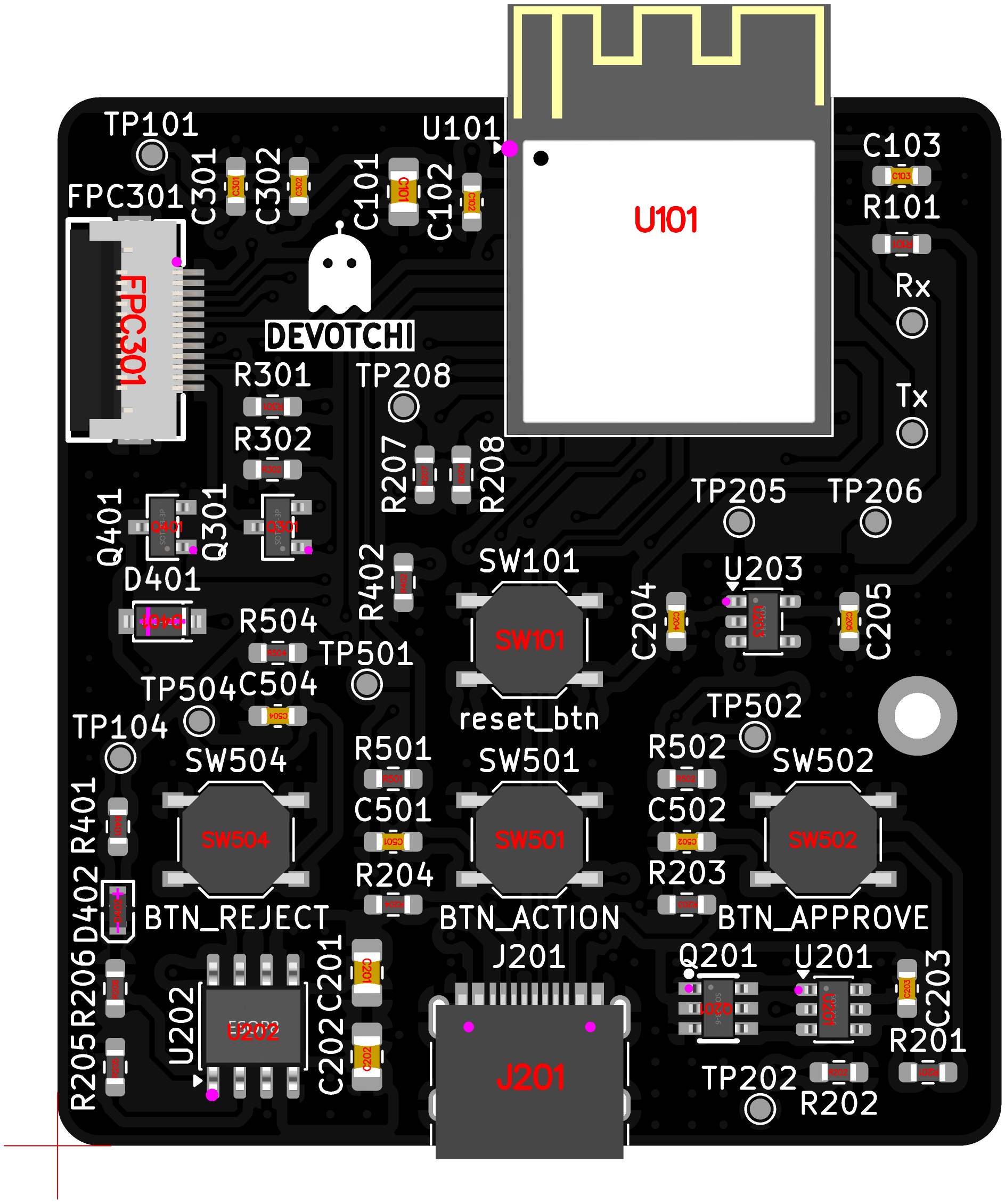
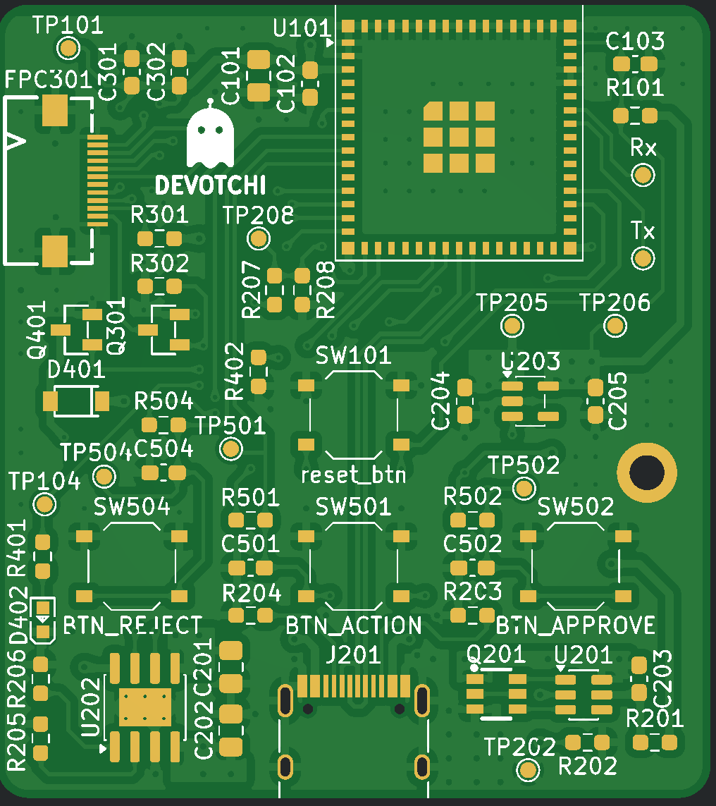
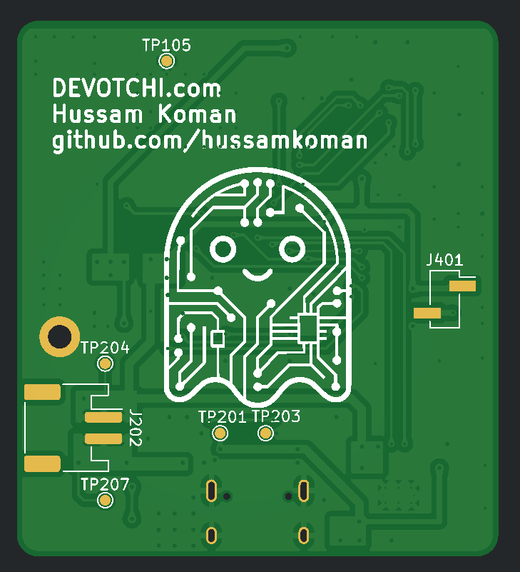
See purchase-list.md for the complete BOM with LCSC part numbers and sourcing info.
| Spec | Value |
|---|---|
| Part number | ESP32-S3-MINI-1-N4R2 (4MB flash, 2MB PSRAM) |
| CPU | Dual-core Xtensa LX7 @ 240 MHz |
| SRAM | 512 KB + 2MB PSRAM |
| WiFi | 802.11 b/g/n, 2.4 GHz |
| Bluetooth | BLE 5.0 |
| Antenna | Integrated PCB antenna |
| Module dimensions | 15.4 x 20.5 x 2.4 mm |
| Operating voltage | 3.0 - 3.6V |
Why N4R2: PSRAM needed for display framebuffers — 320x240 RGB565 = 150KB per frame, double buffering needs 300KB. Without PSRAM, internal 512KB SRAM can't fit framebuffers + WiFi stack + application.
| Spec | Value |
|---|---|
| Manufacturer | HS (Shenzhen Hansheng) |
| Part number | HS20HS072RX |
| LCSC | C5329582 |
| Driver IC | ST7789T3 |
| Size | 2.0 inches diagonal |
| Resolution | 320 x 240 pixels (QVGA) |
| Colors | 262K (RGB666) |
| Pixel pitch | 0.151 x 0.153 mm |
| Active area | 40.80 x 30.60 mm |
| Module size | 51.80 x 36.20 mm |
| Interface | SPI (4-wire) |
| Operating voltage | IOVCC 1.65-3.3V, VCI 2.4-3.3V |
| Backlight | 4 white LEDs in parallel, 80mA max |
| Backlight forward voltage | 3.0V typical (2.8-3.2V) |
| Sleep current | ~30 uA (SLPIN command) |
| Viewing angle | ALL directions (IPS) |
| Contrast ratio | 300:1 typical |
| Connector | 12-pin FPC, 0.5mm pitch |
| Connection type | COG + FPC |
Datasheet: HS20HS072RX datasheet
Source: LCSC/JLCPCB C5329582 — $3.70 (1+), $2.49 (100+), 1687 in stock.
Why this part:
esp_lcd driverFPC pinout:
| Pin | Symbol | Description |
|---|---|---|
| 1 | GND | Power ground |
| 2 | CS | Chip select (active low) |
| 3 | RS (DC) | Data/command select |
| 4 | SCL | SPI clock |
| 5 | SDA | SPI data (MOSI) |
| 6 | RST | Reset (active low) |
| 7 | NC | No connect |
| 8 | IOVCC | I/O logic supply (3.3V) |
| 9 | VCC | Panel power supply (3.3V) |
| 10 | A | Backlight LED anode |
| 11 | K | Backlight LED cathode |
| 12 | GND | Power ground |
Backlight driven from +BATT (3.7-4.2V) through 22Ω resistor + AO3400A N-ch MOSFET, PWM-controlled by ESP32.
Why +BATT instead of 3.3V: LEDs have Vf = 3.0V. Only 0.3V headroom from 3.3V — poor regulation. +BATT gives 0.7-1.2V headroom.
Circuit: +BATT → R (22Ω) → LED anode → LED cathode → MOSFET drain → GND, gate driven by DISP_BL GPIO.
Current at different battery voltages:
Firmware: PWM at 1kHz+. Sleep: SLPIN (0x10) + duty=0. Wake: duty>0 + SLPOUT (0x11), wait 120ms.
Recommended: ESP-IDF native esp_lcd + LovyanGFX
esp_lcd provides the built-in ST7789 panel driver for SPI initializationUSB-C → TP4056 (charger) → DW01A+FS8205A (protection) → ME6211 (3.3V LDO) → ESP32-S3 + display
Datasheets: TP4056 | DW01A | FS8205A | ME6211
Key design notes:
3 tactile switches with hardware debounce (10kΩ pull-up + 100nF cap per button). Active low, pressed = GND. Any button press wakes from deep sleep.
| Button | Function |
|---|---|
| Approve | Accept approval/permission requests |
| Reject | Reject approval/permission requests |
| Action | Context-dependent: scroll, open menu, poke pet |
Strapping pins to avoid: GPIO0 (boot mode), GPIO3 (JTAG source, floating), GPIO45 (VDD_SPI), GPIO46 (boot mode). These are sampled at reset and should not have external loads that could affect their default state during boot.
| Function | ESP32-S3 GPIO | Notes |
|---|---|---|
| SPI Display | ||
| DISP_SCLK | GPIO 12 | SPI clock |
| DISP_MOSI | GPIO 11 | SPI data |
| DISP_CS | GPIO 10 | Chip select |
| DISP_DC | GPIO 9 | Data/command select |
| DISP_RST | GPIO 8 | Reset |
| DISP_BL | GPIO 13 | PWM via MOSFET to backlight cathode |
| Buttons | ||
| BTN_APPROVE | GPIO 4 | Pull-up, active low |
| BTN_REJECT | GPIO 5 | Pull-up, active low |
| BTN_ACTION | GPIO 6 | Pull-up, active low |
| Feedback | ||
| LED_PWM | GPIO 38 | PWM for brightness control |
| MOTOR_EN | GPIO 37 | Via N-channel MOSFET |
| Power status | ||
| PWR_CHRG | GPIO 18 | Low = charging |
| PWR_STDBY | GPIO 17 | Low = charge complete |
| BAT_ADC | GPIO 1 | Via voltage divider for battery level |
| Future (unused, reserved) | ||
| I2S BCLK | GPIO 15 | For microphone (voice commands) |
| I2S WS | GPIO 16 | For microphone |
| I2S DIN | GPIO 2 | For microphone (GPIO 17 used by PWR_STDBY) |
| State | ESP32-S3 | Display | Total | Battery life (500mAh) |
|---|---|---|---|---|
| Active (WiFi on, display on, backlight 100%) | ~80 mA | ~60 mA | ~140 mA | ~3.6 hours |
| Idle (WiFi connected, backlight 25%) | ~20 mA | ~15 mA | ~35 mA | ~14 hours |
| Light sleep (WiFi off, backlight off, LCD sleep) | ~2 mA | ~0.03 mA | ~2 mA | ~250 hours |
| Deep sleep (everything off) | ~8 uA | ~30 uA | ~38 uA | ~1.5 years |
Real-world usage will be a mix — display on for a few seconds when events arrive, then back to sleep. Expected practical battery life: 2-5 days with typical AI coding session activity.
| Qty | Value | Footprint | References |
|---|---|---|---|
| 14 | TestPoint | TestPoint:TestPoint_Pad_D1.0mm | TP101, TP104, TP105, TP201, TP202, TP203, TP204, TP205, TP206, TP207, TP208, TP501, TP502, TP504 |
| 5 | 100n | Capacitor_SMD:C_0603_1608Metric_Pad1.08x0.95mm_HandSolder | C102, C203, C501, C502, C504 |
| 5 | 10k | Resistor_SMD:R_0603_1608Metric_Pad0.98x0.95mm_HandSolder | R101, R206, R501, R502, R504 |
| 5 | 1µ | Capacitor_SMD:C_0603_1608Metric_Pad1.08x0.95mm_HandSolder | C103, C204, C205, C301, C302 |
| 4 | 1k | Resistor_SMD:R_0603_1608Metric_Pad0.98x0.95mm_HandSolder | R201, R202, R302, R402 |
| 2 | 100k | Resistor_SMD:R_0603_1608Metric_Pad0.98x0.95mm_HandSolder | R207, R208 |
| 2 | 10µ | Capacitor_SMD:C_0805_2012Metric_Pad1.18x1.45mm_HandSolder | C201, C202 |
| 2 | 5k1 | Resistor_SMD:R_0603_1608Metric_Pad0.98x0.95mm_HandSolder | R203, R204 |
| 2 | AO3400A | easyeda:SOT-23-3_L2.9-W1.3-P1.90-LS2.4-BR | Q301, Q401 |
| 1 | 150R | Resistor_SMD:R_0603_1608Metric_Pad0.98x0.95mm_HandSolder | R401 |
| 1 | 1N5819W S4_C42441798 | easyeda:SOD-123_L2.7-W1.6-LS3.7-RD | D401 |
| 1 | 22R | Resistor_SMD:R_0603_1608Metric_Pad0.98x0.95mm_HandSolder | R301 |
| 1 | 22µ | Capacitor_SMD:C_0805_2012Metric_Pad1.18x1.45mm_HandSolder | C101 |
| 1 | 3k | Resistor_SMD:R_0603_1608Metric_Pad0.98x0.95mm_HandSolder | R205 |
| 1 | AFC01-S12FCA-00 | easyeda:FPC-SMD_AFC01-S12FCA-00 | FPC301 |
| 1 | BTN_ACTION | Button_Switch_SMD:SW_Push_1P1T_XKB_TS-1187A | SW501 |
| 1 | BTN_APPROVE | Button_Switch_SMD:SW_Push_1P1T_XKB_TS-1187A | SW502 |
| 1 | BTN_REJECT | Button_Switch_SMD:SW_Push_1P1T_XKB_TS-1187A | SW504 |
| 1 | Battery_conn | Connector_JST:JST_PH_S2B-PH-SM4-TB_1x02-1MP_P2.00mm_Horizontal | J202 |
| 1 | DW01A | Package_TO_SOT_SMD:SOT-23-6 | U201 |
| 1 | ESP32-S3-MINI-1-N4R2 | RF_Module:ESP32-S2-MINI-1 | U101 |
| 1 | FC-1608G1-520 | easyeda:LED0603-RD | D402 |
| 1 | FS8205A_C2830320 | easyeda:SOT-23-6_L2.9-W1.6-P0.95-LS2.8-BR | Q201 |
| 1 | HS20HS072RX | easyeda:OLED-SMD_HS20HS072RX | U301 |
| 1 | LOGO | libs:ghost_logo | G*** |
| 1 | LOGO | libs:ghost_logo2 | G*** |
| 1 | ME6211C33M5 | Package_TO_SOT_SMD:SOT-23-5 | U203 |
| 1 | Motor | Connector_PinHeader_2.54mm:PinHeader_1x02_P2.54mm_Vertical_SMD_Pin1Right | J401 |
| 1 | MountingHole_Pad | MountingHole:MountingHole_2.2mm_M2_DIN965_Pad | H101 |
| 1 | Rx | TestPoint:TestPoint_Pad_D1.0mm | TP103 |
| 1 | TP4056-42-ESOP8 | Package_SO:SOIC-8-1EP_3.9x4.9mm_P1.27mm_EP2.41x3.3mm_ThermalVias | U202 |
| 1 | Tx | TestPoint:TestPoint_Pad_D1.0mm | TP102 |
| 1 | USB_C_Receptacle_USB2.0_16P | Connector_USB:USB_C_Receptacle_HRO_TYPE-C-31-M-12 | J201 |
| 1 | reset_btn | Button_Switch_SMD:SW_Push_1P1T_XKB_TS-1187A | SW101 |
It measures 45 × 50 mm and has 4 copper layers, 1.61 mm thick.
66 parts, built around the ESP32-S3-MINI-1-N4R2, DW01A, HS20HS072RX and ME6211C33M5G-N. The full list of its parts is on this page, with links to each part's symbol and footprint where PCBKit's library has them.
From the hussamkoman/devotchi repository on GitHub, at the commit this page was made from: the board is hardware/devotchi.kicad_pcb and its schematic hardware/devotchi.kicad_sch. PCBKit opens the board in the browser, with nothing to install.
Its repository publishes it under the MIT licence: you may reuse it on that licence's terms (keep the author's notice, and for a copyleft licence share your changes alike).
Miroeilola/vallox-rs485-controller
Replacement control panel for legacy Vallox SE ventilation units. Vallox DIGIT RS-485 protocol, bus-powered, ESP32, Home Assistant.

dark-Phoenix2077/voidboard
custom esp32 devboard with extensive power management and a built-in IMU


saptak70/Nindo-Handheld-gameboy-and-mp3-player--using-esp32
A custom handheld device built from scratch — PCB, firmware, and enclosure. Plays NES/DOOM, streams audio to BT headphones.

Witosworld/Roboterarm_Fernbedienung
Robotarm controller with an IMU via ESP now.

HenraL/panic_button
This is an attempt at creating a box that aims to allow you to broacast your location to someone close like the other deivces (air tag, tile, etc) but as it is not a brand and uses the internet instead of ble and an…

GuzziFlipFlops/ESP32-Walkie-Talkie
An open source ESPNOW based walkie talkie with a 600 meter tested distance, with an OLED and multiple buttons to interact with

Yang-xy-svg/ESP_OpenMic
This project is subject to the licence in the LICENCE file, and even if that says it is an open source project, you cannot sell boards or cases bearing the Andrews & Arnold Ltd name, the A&A logo, the registered…