2 layers100 × 80 mm
Smart Home Controller
Ajith-Anand-R/Smart-Home-Controller
Full-stack IoT home automation system with ESP32 firmware, Google Apps Script backend, web dashboard, and Flutter mobile app.
11 parts1MIT

 HuibSmeets/PulseFlow1
Control a fan speed by heart rate
PulseFlow - PCB is an open-source printed circuit board by HuibSmeets, from the HuibSmeets/PulseFlow repository on GitHub, published under the GPL-3.0 licence. It is a 2-layer board of 95 × 60 mm with 28 parts on 55 nets, routed with 175 tracks and 2 vias.
It is built around the BT136-600E, IRM-03-9 and MOC3021, with the SFH620A-3 and ULN2003A among its other parts. Its parts include 12 resistors, 3 ICs, 3 connectors, 2 capacitors and 1 transistor. It belongs with the radio and wireless and sensors and measurement boards and the AVR (ATmega, ATtiny) boards of this library.


Control the speed of a cooling fan with your heart rate while riding/using your indoor trainer.
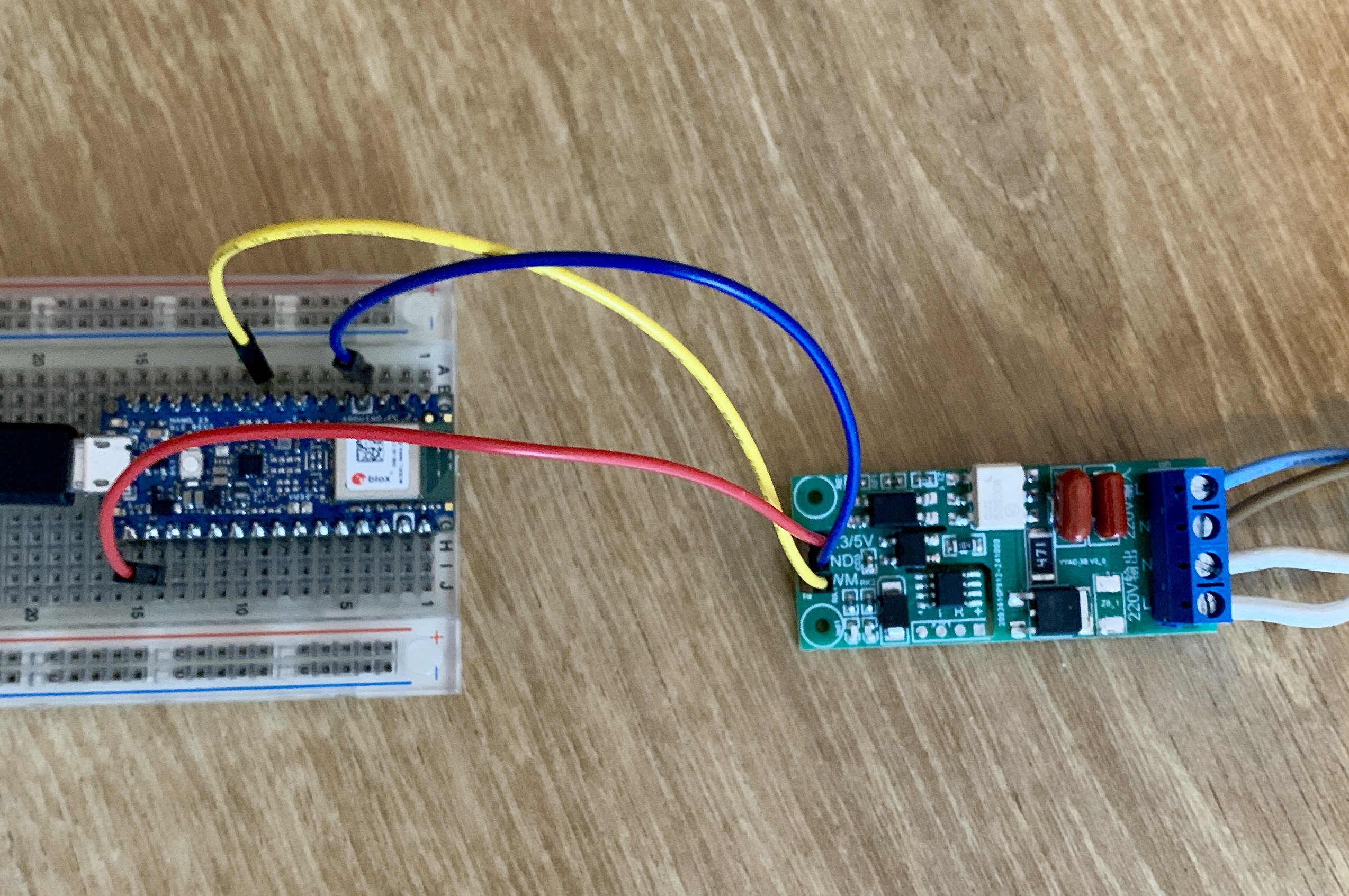 Image: Prototype, work in progress
PulseFlow is a small Arduino sketch that connects via BLE to a HR fitness sensor like those from Garmin, Wahoo and others. The fan is connected to a PWM controllable AC dimmer or a dimmer that exposes 2 pins: Output Zerocross detection, input triac trigger. These AC dimmers can be sourced from marketplaces like AliExpress.
BE AWARE THAT YOU'LL BE WORKING WITH DEADLY LIVE VOLTAGES. TAKE APPROPRIATE SAFETY MEASURES WHEN CONNECTING PARTS AND WHILE USING THE DEVICE YOU CREATED.
| Qty | Value | Footprint | References |
|---|---|---|---|
| 4 | MountingHole | MountingHole:MountingHole_3.2mm_M3_ISO14580 | H1, H2, H3, H4 |
| 3 | 4K7 | Resistor_THT:R_Axial_DIN0207_L6.3mm_D2.5mm_P10.16mm_Horizontal | R5, R11, R12 |
| 2 | 15K/1W | Resistor_THT:R_Axial_DIN0207_L6.3mm_D2.5mm_P10.16mm_Horizontal | R7, R8 |
| 2 | 290R | Resistor_THT:R_Axial_DIN0207_L6.3mm_D2.5mm_P10.16mm_Horizontal | R2, R3 |
| 2 | Screw_Terminal_01x04 | TerminalBlock_Phoenix:TerminalBlock_Phoenix_MPT-0,5-4-2.54_1x04_P2.54mm_Horizontal | J1, J2 |
| 1 | 0.01 uF/400V | Capacitor_THT:C_Rect_L10.0mm_W4.0mm_P7.50mm_FKS3_FKP3 | C4 |
| 1 | 0.05uF/400V | Capacitor_THT:C_Rect_L13.0mm_W6.0mm_P10.00mm_FKS3_FKP3_MKS4 | C3 |
| 1 | 330R | Resistor_THT:R_Axial_DIN0207_L6.3mm_D2.5mm_P10.16mm_Horizontal | R1 |
| 1 | 360R | Resistor_THT:R_Axial_DIN0207_L6.3mm_D2.5mm_P10.16mm_Horizontal | R4 |
| 1 | 360R/1W | Resistor_THT:R_Axial_DIN0207_L6.3mm_D2.5mm_P10.16mm_Horizontal | R6 |
| 1 | 39R/1W | Resistor_THT:R_Axial_DIN0207_L6.3mm_D2.5mm_P10.16mm_Horizontal | R10 |
| 1 | 470R/1W | Resistor_THT:R_Axial_DIN0207_L6.3mm_D2.5mm_P10.16mm_Horizontal | R9 |
| 1 | Arduino_Nano_33_BLE_Rev2 | MyFootPrints:Arduino_Nano_WithMountingHoles | ARD1 |
| 1 | BT136-600 | Package_TO_SOT_THT:TO-220-3_Vertical | Q1 |
| 1 | Heatsink_Pad | MyFootPrints:Heatsink_Fischer_SK-431-1x25mm | HS1 |
| 1 | IRM-03-9 | Converter_ACDC:Converter_ACDC_MeanWell_IRM-03-xx_THT | PS1 |
| 1 | MOC3021 | Package_DIP:DIP-6_W7.62mm | U2 |
| 1 | SFH620A-3 | Package_DIP:DIP-4_W7.62mm | U3 |
| 1 | Screw_Terminal_01x04 | TerminalBlock_Phoenix:TerminalBlock_Phoenix_MKDS-1,5-4-5.08_1x04_P5.08mm_Horizontal | J3 |
| 1 | ULN2003A | Package_DIP:DIP-16_W7.62mm | U1 |
It measures 95 × 60 mm and has 2 copper layers, 1.6 mm thick.
28 parts, built around the BT136-600E, IRM-03-9, MOC3021 and SFH620A-3. The full list of its parts is on this page, with links to each part's symbol and footprint where PCBKit's library has them.
From the HuibSmeets/PulseFlow repository on GitHub, at the commit this page was made from: the board is pcb/PulseFlow - PCB.kicad_pcb and its schematic pcb/PulseFlow - PCB.kicad_sch. PCBKit opens the board in the browser, with nothing to install.
Its repository publishes it under the GPL-3.0 licence: you may reuse it on that licence's terms (keep the author's notice, and for a copyleft licence share your changes alike).
Ajith-Anand-R/Smart-Home-Controller
Full-stack IoT home automation system with ESP32 firmware, Google Apps Script backend, web dashboard, and Flutter mobile app.

KevinAR-18/EcoLab-Dashboard
EcoLab Dashboard is a smart laboratory EcoLab desktop application for real-time monitoring and control of laboratory devices within the UGM network.


Loic74650/ioBoard
A relay (and more!) board with Ethernet connectivity and MQTT support

gregorv/sousvide
Hardware and software for an ATmega8 based Sous-Vide temperature controller


