2 layers130 × 83.9 mm

 hkzlab/NoCIC4
Replacement CIC for NES consoles with reliable reset timing
NoCIC is an open-source printed circuit board by hkzlab, from the hkzlab/NoCIC repository on GitHub. It is a 2-layer board of 9.5 × 20.6 mm with 15 parts on 20 nets, routed with 109 tracks and 14 vias.
It is built around the 74LVC1G06Z and 74LVC1G04Z. Its parts include 5 capacitors, 5 resistors, 3 ICs and 1 connector. It belongs with the retro computing and games boards of this library.

Any use of this project is under your own responsibility. You will be responsible of checking the correct construction and functionality of your board. By using this project You will agree that I cannot be held responsible if it will destroy any of your devices, damage your computer, burn down your house or whatever.

This project is kindly sponsored by PCBWay. PCBWay specializes in manufacturing high-quality PCBs and makes them affordable to hobbyist and professionals alike.
The range of services they offer include PCB prototyping, assembly, instant quotes for your order, a verification process by a team of experts and an easy to use, hassle-free order process.
I'm grateful to PCBWay for the help in evolving and testing this project. You can order the currently released revisions of the board from them, see the link below!
This is a replacement of the NES CIC IC that implements the reset functionality, fits in a DIP16 footprint and... nothing else.
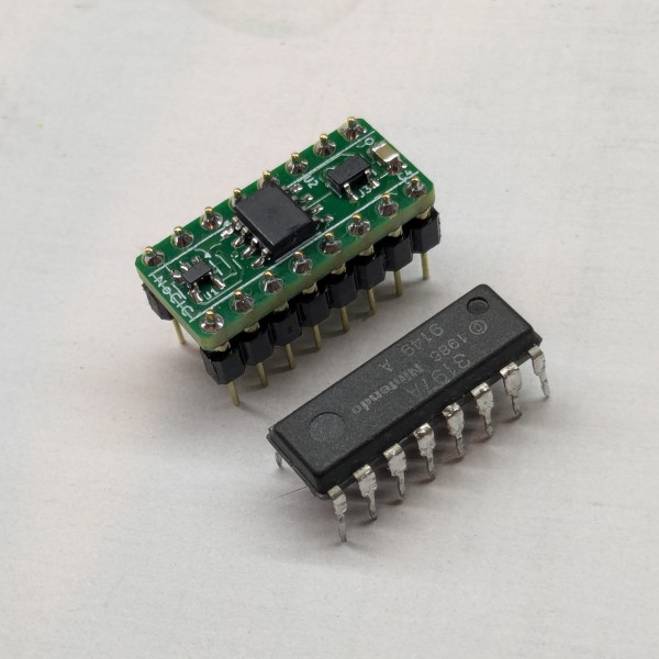
The NullCIC already does this, but I faced some issues with it where the NES sometimes failed to startup properly during a cold boot, and required a manual reset (possibly related to timing of my specific motherboard, even though the issues were not present with an original CIC installed).
Tweaking the cap and bodging a resistor on the NullCIC alleviated the issue by a lot, but I decided to go with something that allowed me to control the reset timing a bit more reliably, and went with a classic 555 circuit.
The values for the components in the BOM should provide around 500ms of time in reset at startup.
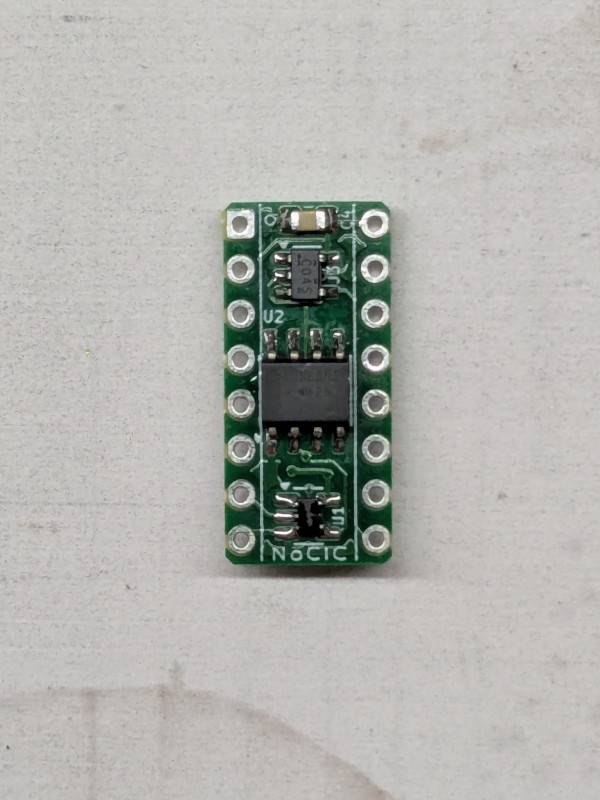
This board was tested with two of my NES units without issues, let me know if it works for you!
The board was designed with KiCad EDA.
| Component | Qty | Type / Value | Notes |
|---|---|---|---|
| U1 | 1 | 74LVC1G06 / SOT-23-5 | |
| U2 | 1 | 555, CMOS, SOIC-8 | |
| U3 | 1 | 74LVC1G04 / SOT-23-5 | |
| C1, C4 | 2 | 100nF / 16V+ / 0805 | MLCC |
| C2 | 1 | 10nF / 16V+ / 0805 | MLCC |
| C3 | 1 | 10uF / 16V+ / 0805 | MLCC |
| C5 | 1 | 470nF / 16V+ / 0805 | MLCC |
| R1 | 1 | 10K / 0805 | |
| R2 | 1 | 1M / 0805 | |
| R3 | 1 | 47K / 0805 | |
| R4, R5 | 2 | 2K ~ 10K / 0805 | Optional pull-downs for DI and DO, in case a fake CIC in the cart attempts to glitch us with spikes |
| J1 | 2 | 8pin machined headers, 2.54mm pitch | Mount on the underside |
JP1 can be optionally jumpered to allow the 555 to reset the CIC in the cart.
You can order the board for this project at PCBWay and support me or download the gerbers and have them printed wherever you like!!!
I you want to contact me about selling this project, you can reach me via email at 0hkzUNDERSCOREprojects6ATposteoDOTnet after properly fixing the email address by removing the digits and replacing the uppercase words with the proper characters.
Contacts via other channels will be ignored, as it means you did not read this document thoroughly.
"Collaborations" will boil down to the following:
If this is not ok for you, you're cordially invited to go bother someone else :)
Authorized sellers will be listed in this README. If you find someone selling my boards without being listed here, it means they're stealing other people's work.
| Qty | Value | Footprint | References |
|---|---|---|---|
| 2 | 100nF | Capacitor_SMD:C_0805_2012Metric_Pad1.18x1.45mm_HandSolder | C1, C4 |
| 2 | 1K | Resistor_SMD:R_0805_2012Metric_Pad1.20x1.40mm_HandSolder | R4, R5 |
| 1 | 10K | Resistor_SMD:R_0805_2012Metric_Pad1.20x1.40mm_HandSolder | R1 |
| 1 | 10nF | Capacitor_SMD:C_0805_2012Metric_Pad1.18x1.45mm_HandSolder | C2 |
| 1 | 10uF | Capacitor_SMD:C_0805_2012Metric_Pad1.18x1.45mm_HandSolder | C3 |
| 1 | 1M | Resistor_SMD:R_0805_2012Metric_Pad1.20x1.40mm_HandSolder | R2 |
| 1 | 470nF | Capacitor_SMD:C_0805_2012Metric_Pad1.18x1.45mm_HandSolder | C5 |
| 1 | 47K | Resistor_SMD:R_0805_2012Metric_Pad1.20x1.40mm_HandSolder | R3 |
| 1 | 74LVC1G04 | Package_TO_SOT_SMD:SOT-23-5 | U3 |
| 1 | 74LVC1G06 | Package_TO_SOT_SMD:SOT-23-5 | U1 |
| 1 | CIC | Package_DIP:DIP-16_W7.62mm | J1 |
| 1 | CIC-RESET Enabled | Jumper:SolderJumper-2_P1.3mm_Open_RoundedPad1.0x1.5mm | JP1 |
| 1 | LMC555xM | Package_SO:SOIC-8_3.9x4.9mm_P1.27mm | U2 |

greatscottgadgets/urti-mainboard
Mainboard of URTI, the Universal Radio Test Instrument


yyzkevin/PicoPCMCIA-Breakout
The PicoPCMCIA External I/O uses Hirose ST-series connectors, chosen for their compact size and robust locking mechanism.
It measures 9.5 × 20.6 mm and has 2 copper layers, 1.6 mm thick.
15 parts, built around the 74LVC1G06Z and 74LVC1G04Z. The full list of its parts is on this page, with links to each part's symbol and footprint where PCBKit's library has them.
From the hkzlab/NoCIC repository on GitHub, at the commit this page was made from: the board is NoCIC.kicad_pcb and its schematic NoCIC.kicad_sch. PCBKit opens the board in the browser, with nothing to install.
Its repository states no licence, so its author keeps all rights: ask hkzlab before reusing the design.