2 layers71 × 73 mm
Alarm
bbokser/persuasive_waker
An open source hardware alarm clock that can't be snoozed or turned off.
71 parts3MIT

 hkienle/osh-vacuum8
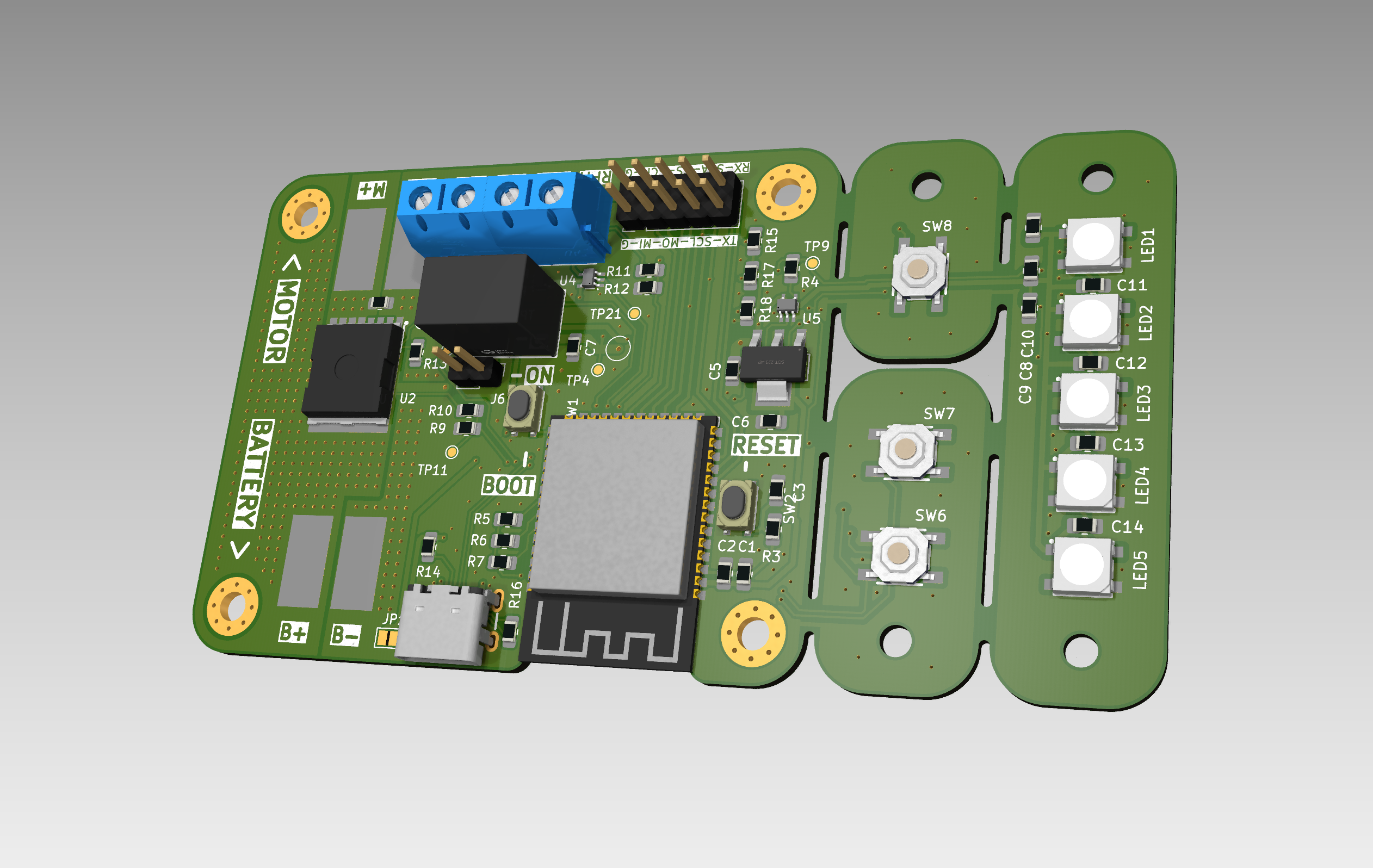
This PCB is designed to control a high RPM impeller for vacuum machines. It provides comprehensive control and monitoring capabilities with modern connectivity options.
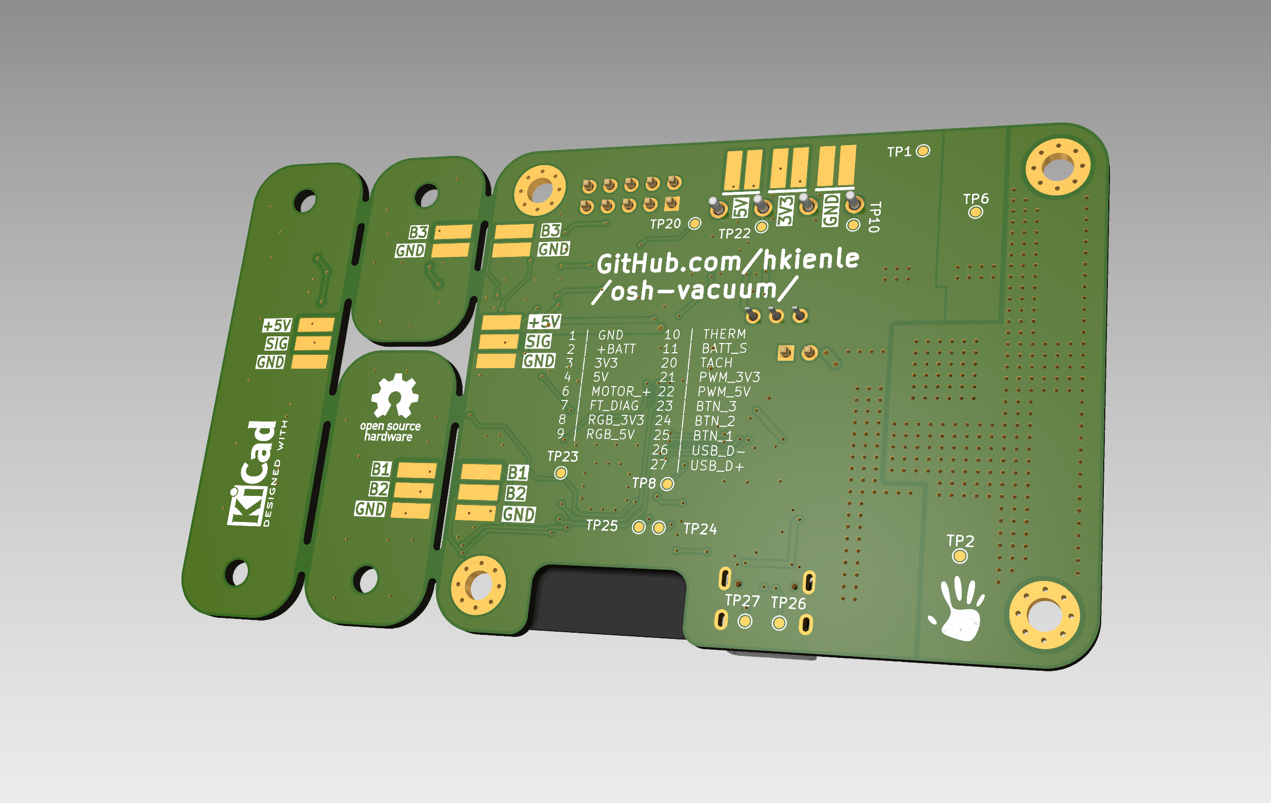
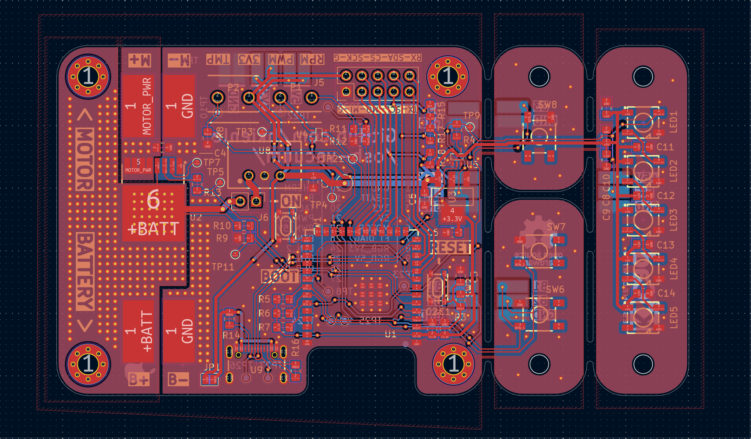
Benchtop V1 is an open-source printed circuit board by hkienle, from the hkienle/osh-vacuum repository on GitHub. It is a 2-layer board of 101 × 56 mm with 82 parts on 65 nets, routed with 635 tracks and 485 vias.
It is built around the SN74AHCT1G125DCKR(LX), 12402012E212A and BTH500151LUAAUMA1, with the LD1117S33CTR-HXY, WS2812B-V5/W and TS-1076S-A7B3 among its other parts. Its parts include 16 resistors, 14 capacitors, 8 connectors, 7 ICs and 5 diodes. It belongs with the ESP32 boards of this library.


Status: Untested - This board is currently in the benchtop prototype phase of the Open Source Vacuum Cleaner project and has not yet been tested.
This PCB is designed to control a high RPM impeller for vacuum machines. It provides comprehensive control and monitoring capabilities with modern connectivity options.
The design features break-off sections that allow users to build their own vacuum cleaner in whichever shape they like. These break-off sections enable flexible placement of LEDs and buttons to suit various form factors and user preferences.
Connectivity
Power Management
User Interface
Motor Control & Monitoring
Expansion
| Designator | Footprint | Quantity | Value | LCSC Part # |
|---|---|---|---|---|
| C1, C7, C8, C9 | 0805 | 4 | 22µF | - |
| C10, C11, C12, C13, C14, C2, C5 | 0805 | 7 | 0.1µF | - |
| C3 | 0805 | 1 | 1µF | - |
| C4 | 0805 | 1 | 10nF | - |
| C6 | 0805 | 1 | 10µF | - |
| LED1, LED2, LED3, LED4, LED5 | LED-SMD_4P-L5.0-W5.0-TL-1 | 5 | WS2812B-V5/W | C2874885 |
| R10 | 0805 | 1 | 330kΩ | - |
| R11 | 0805 | 1 | 33kΩ | - |
| R12 | 0805 | 1 | 56kΩ | - |
| R13 | 0805 | 1 | 4.7kΩ | - |
| R14, R16 | 0805 | 2 | 5.1kΩ | - |
| R15, R17, R18, R3, R5, R6, R7, R8 | 0805 | 8 | 10kΩ | - |
| R4 | 0805 | 1 | 220Ω | - |
| R9 | 0805 | 1 | 22kΩ | - |
| SW1, SW2 | SW-SMD_4P-L4.2-W3.2-P2.15-LS4.6 | 2 | RKB2SJK250SMTRLFS | C2927789 |
| SW6, SW7, SW8 | KEY-SMD_4P-L5.2-W5.2-P3.7-LS6.4-TL | 3 | TS-1076S-A7B3 | C492950 |
| U1 | WIRELM-SMD_ESP32-S3-WROOM-1 | 1 | ESP32-S3-WROOM-1(N16R2) | C2913205 |
| U2 | PG-HSOF-8_L10.4-W9.8-BTH500151LUAAUMA1 | 1 | BTH500151LUAAUMA1 | C36571656 |
| U3 | SOT-223-4_L6.5-W3.5-P2.30-LS7.0-BR | 1 | LD1117S33CTR | C35879 |
| U4, U5 | SC-70-5_L2.0-W1.3-P0.65-LS2.1-BL | 2 | SN74AHCT1G125DCKR | C350557 |
| U8 | PWRM-TH_L11.7-W7.5_TSR1-2450 | 1 | TSR 1-2450_C6886877 | C6886877 |
| U9 | USB-SMD_TYPE-C16PIN-1 | 1 | 12402012E212A | C5150972 |
This hardware design is licensed under the CERN Open Hardware Licence - Strongly Reciprocal (CERN OHL-S v2).
The full license text is available at: cern_ohl_s_v2.txt
| Qty | Value | Footprint | References |
|---|---|---|---|
| 19 | TestPoint | TestPoint:TestPoint_Pad_D1.0mm | TP1, TP2, TP3, TP4, TP5, TP6, TP10, TP11, TP20, TP21, TP22, TP23, TP24, TP25, TP26, TP27 +3 |
| 8 | 10k | Resistor_SMD:R_0805_2012Metric_Pad1.20x1.40mm_HandSolder | R3, R5, R6, R7, R8, R15, R17, R18 |
| 7 | 0.1uF | Resistor_SMD:R_0805_2012Metric_Pad1.20x1.40mm_HandSolder | C2, C5, C10, C11, C12, C13, C14 |
| 5 | WS2812B-V5/W | easyeda2kicad:LED-SMD_4P-L5.0-W5.0-TL-1 | LED1, LED2, LED3, LED4, LED5 |
| 4 | 22uF | Resistor_SMD:R_0805_2012Metric_Pad1.20x1.40mm_HandSolder | C1, C7, C8, C9 |
| 4 | Conn_01x01_Pin | Connector_Wire:SolderWirePad_1x01_SMD_5x10mm | J1, J2, J3, J4 |
| 4 | MountingHole | MountingHole:MountingHole_3.2mm_M3_Pad_Via | H1, H2, H3, H4 |
| 3 | TS-1076S-A7B3 | easyeda2kicad:KEY-SMD_4P-L5.2-W5.2-P3.7-LS6.4-TL | SW6, SW7, SW8 |
| 2 | 5.1k | Resistor_SMD:R_0805_2012Metric_Pad1.20x1.40mm_HandSolder | R14, R16 |
| 2 | RKB2SJK250SMTRLFS | easyeda2kicad:SW-SMD_4P-L4.2-W3.2-P2.15-LS4.6 | SW1, SW2 |
| 2 | SN74AHCT1G125DCKR | easyeda2kicad:SC-70-5_L2.0-W1.3-P0.65-LS2.1-BL | U4, U5 |
| 2 | WJ301V-5.0-2P | easyeda2kicad:CONN-TH_2P-P5.00_WJ301V-5.00-2P | P1, P2 |
| 1 | 10nF | Resistor_SMD:R_0805_2012Metric_Pad1.20x1.40mm_HandSolder | C4 |
| 1 | 10uF | Resistor_SMD:R_0805_2012Metric_Pad1.20x1.40mm_HandSolder | C6 |
| 1 | 12402012E212A | easyeda2kicad:USB-SMD_TYPE-C16PIN-1 | U9 |
| 1 | 1uF | Resistor_SMD:R_0805_2012Metric_Pad1.20x1.40mm_HandSolder | C3 |
| 1 | 220R | Resistor_SMD:R_0805_2012Metric_Pad1.20x1.40mm_HandSolder | R4 |
| 1 | 22k | Resistor_SMD:R_0805_2012Metric_Pad1.20x1.40mm_HandSolder | R9 |
| 1 | 330k | Resistor_SMD:R_0805_2012Metric_Pad1.20x1.40mm_HandSolder | R10 |
| 1 | 33k | Resistor_SMD:R_0805_2012Metric_Pad1.20x1.40mm_HandSolder | R11 |
| 1 | 4.7k | Resistor_SMD:R_0805_2012Metric_Pad1.20x1.40mm_HandSolder | R13 |
| 1 | 56k | Resistor_SMD:R_0805_2012Metric_Pad1.20x1.40mm_HandSolder | R12 |
| 1 | BTH500151LUAAUMA1 | easyeda2kicad:PG-HSOF-8_L10.4-W9.8-BTH500151LUAAUMA1 | U2 |
| 1 | Conn_01x02_Pin | Connector_PinHeader_2.54mm:PinHeader_1x02_P2.54mm_Vertical | J6 |
| 1 | Conn_01x10 | Connector_PinHeader_2.54mm:PinHeader_2x05_P2.54mm_Vertical | J5 |
| 1 | ESP32-S3-WROOM-1(N16R2) | easyeda2kicad:WIRELM-SMD_ESP32-S3-WROOM-1 | U1 |
| 1 | LD1117S33CTR | easyeda2kicad:SOT-223-4_L6.5-W3.5-P2.30-LS7.0-BR | U3 |
| 1 | LOGO | Logos:intuity_logo_hand | G*** |
| 1 | SolderJumper_2_Open | Jumper:SolderJumper-2_P1.3mm_Open_Pad1.0x1.5mm | JP1 |
| 1 | TSR 1-2450_C6886877 | easyeda2kicad:PWRM-TH_L11.7-W7.5_TSR1-2450 | U8 |
The 80 most common of 82 parts.
bbokser/persuasive_waker
An open source hardware alarm clock that can't be snoozed or turned off.

Dfdye/Voron_Mods
The parts in this repository have been designed for my own use, and not specifically for public release. As such, they probably contain multiple errors, and are subject to change without notice.

Maritime-Hacking-Village/Badge-2025
Public repository for the official MHV 2025 badge.

doenertrinker909/Makropad
A macropad featuring a 4x4 grid of keys, two rotary encoders and a 128x32 OLED display


Jochen0x90h/LedStrip
Receiver and voltage regulator for LED strips based on WS2812 or equivalent

It measures 101 × 56 mm and has 2 copper layers, 1.6 mm thick.
82 parts, built around the SN74AHCT1G125DCKR(LX), 12402012E212A, BTH500151LUAAUMA1 and LD1117S33CTR-HXY. The full list of its parts is on this page, with links to each part's symbol and footprint where PCBKit's library has them.
From the hkienle/osh-vacuum repository on GitHub, at the commit this page was made from: the board is Hardware/PCB_Bench_Prototype/Benchtop_V1.kicad_pcb and its schematic Hardware/PCB_Bench_Prototype/Benchtop_V1.kicad_sch. PCBKit opens the board in the browser, with nothing to install.
Its repository states no licence, so its author keeps all rights: ask hkienle before reusing the design.