2 layers0.7 × 0.5 mm

 HexFud/HexArm
I created this 6 axis robotic arm entirely from scratch starting from the PCB to the 3D modelling and designing.
6axis robot is an open-source printed circuit board by HexFud, from the HexFud/HexArm repository on GitHub. It is a 4-layer board of 124.4 × 115.3 mm with 97 parts on 107 nets, routed with 1,693 tracks and 249 vias.
It is built around the SN65HVD230D, TPS54331D and AMS1117-3.3, with the AO4407A, B340 and SMBJ36A among its other parts. Its parts include 33 capacitors, 24 connectors, 21 resistors, 5 ICs and 4 diodes. It belongs with the robots and motor control boards and the STM32 boards of this library.


I created this 6 axis robotic arm entirely from scratch starting from the PCB to the 3D modelling and designing.
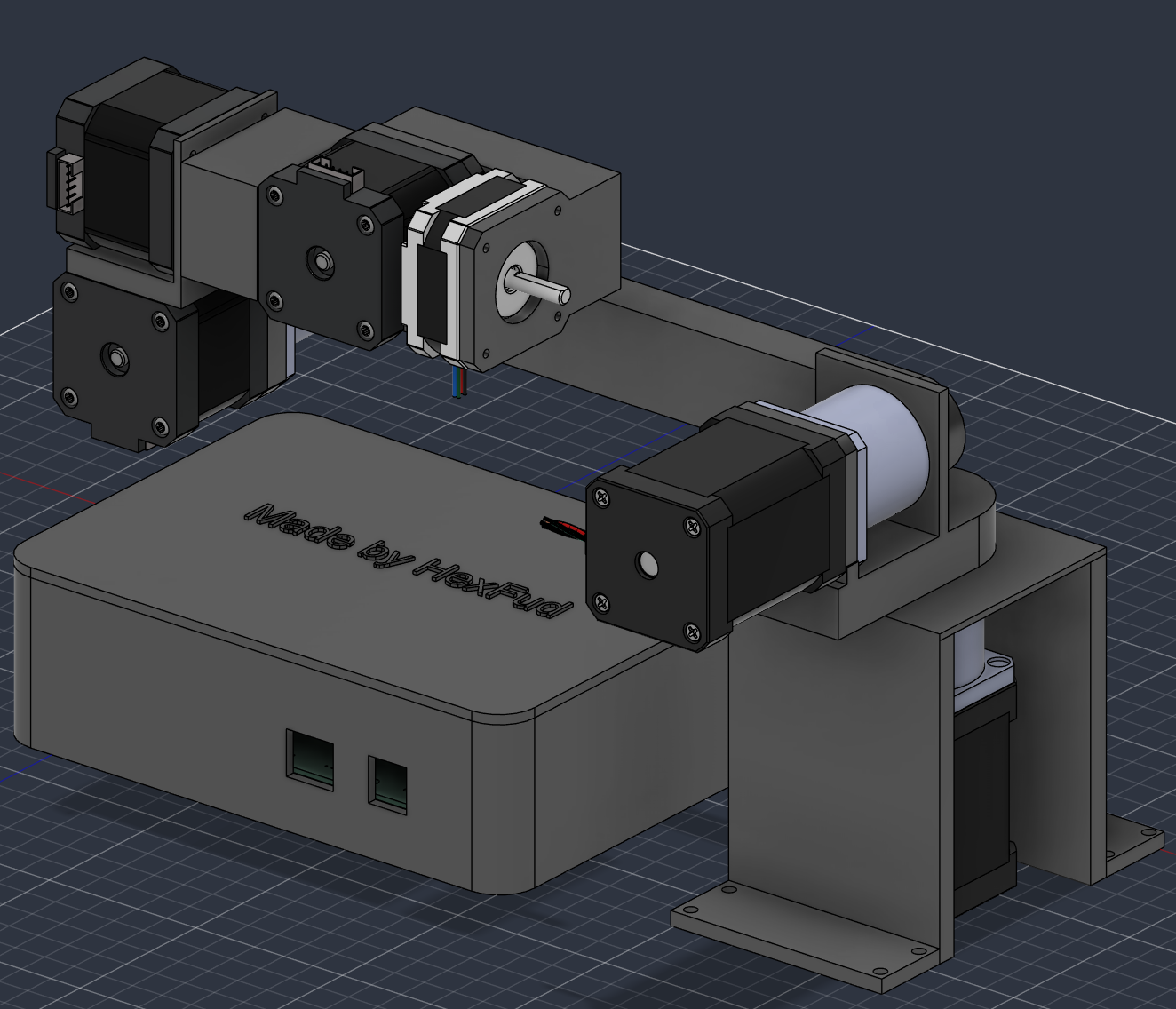
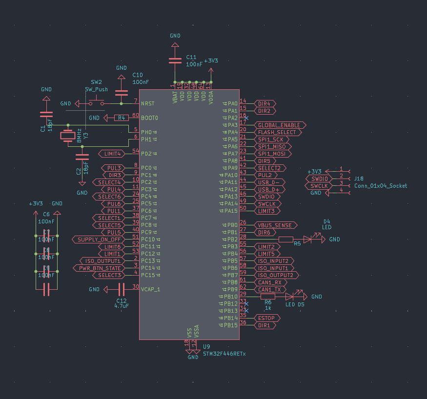
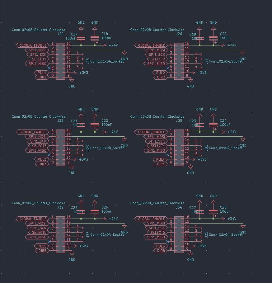
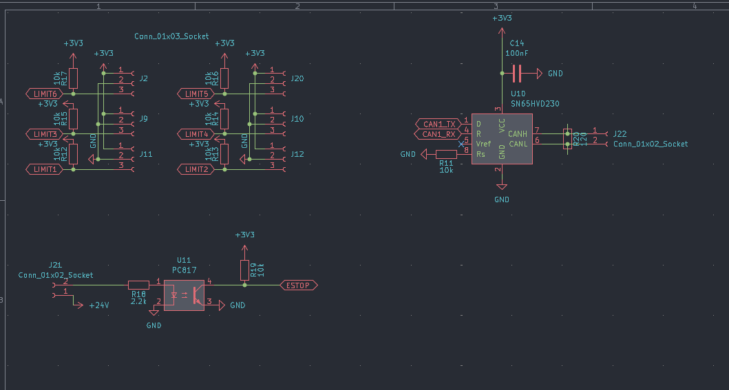
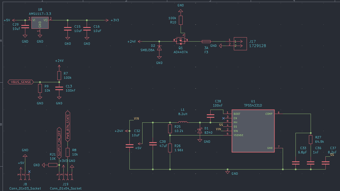
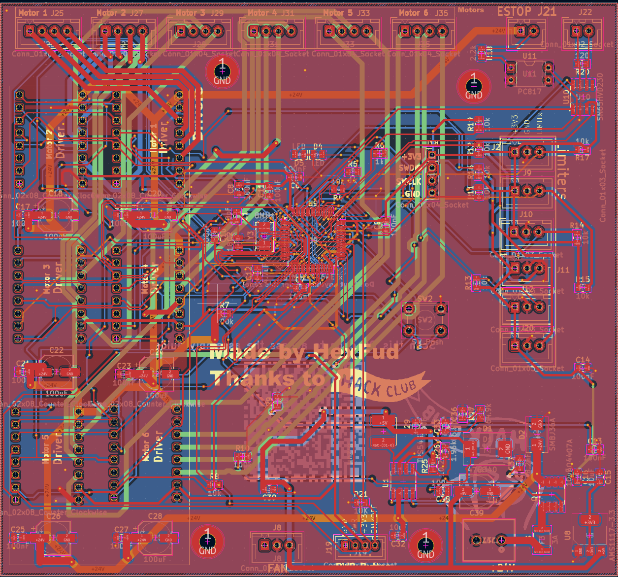
I designed the PCB that can take up to 6 motors (I used 6 NEMA 17) with 6 driver boards that you can directly plug into the PCB. In the PCB case there is a cutout for a 40mm fan directly pluggable into the dedicated +5V socket (identified by FAN or J8 connector), this is foundamental to keep the motor drivers cool and keep things as safe as possible. The board runs on 24V connection and includes connections for:
| Pin | Function | Where to connect |
|---|---|---|
| 1 | GND | Switch contact + LED Negative (-) wire |
| 2 | PWR | Switch contact |
| 3 | +3V3 | LED Positive (+) wire |
| 4 | Reserved | Do not connect any wire to it |
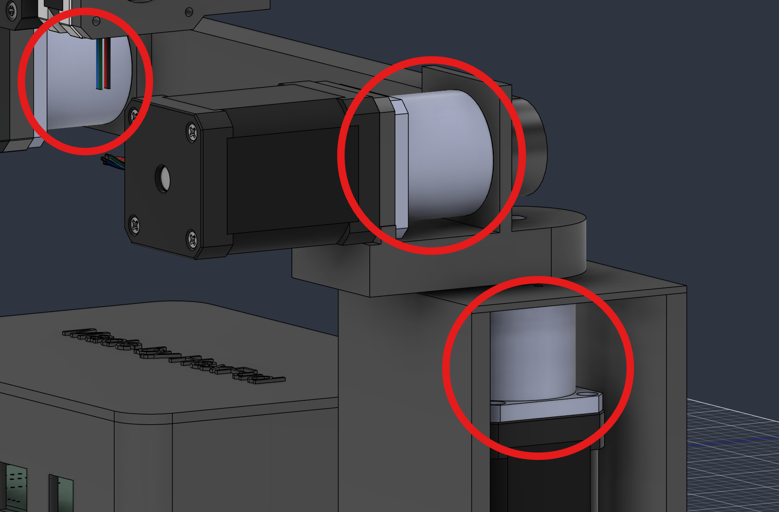
To make sure the arm can lift certain payloads wihout struggling I preferred to not use a direct-drive style to move the joints, this is why for the most heavy and tourqe demanding parts I paired the NEMA 17 motors with 20:1 and 10:1 gearboxes (you can see them marked in red)
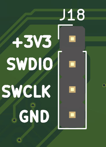
My project doesn't have a USB-C or other type of interfaces so to flash the firmware you need a ST-LINK V2 where you need to wire up the correct cable from the usb to the board (J18 connector) and download the free software STM32CubeProgrammer and you simply need to upload the firmware.
Steps to reproduce (note that you need to do both):
In Arduino IDE:
In STM32CubeProgrammer:
Because stepper motors and the drivers generate heat around 50°C-60°C I strongly reccomend to use filaments like PETG, ABS or ASA instead of standard PLA ensuring the plastic won't soften, warp or melt during intensive load.
This project includes experimental software, hardware designs, and assembly documentation are still under development and may contain bugs, errors, or incomplete features. By using, building, or modifying this project, you acknowledge that:
By proceeding, you accept all risks and agree to these conditions. If you do not acknowledge these risks and conditions, please do not use or build this project.
| Qty | Value | Footprint | References |
|---|---|---|---|
| 15 | 100nF | Capacitor_SMD:C_0805_2012Metric | C6, C7, C8, C9, C10, C11, C13, C14, C17, C19, C21, C23, C25, C27, C38 |
| 11 | 10k | Resistor_SMD:R_0805_2012Metric | R4, R8, R9, R11, R12, R13, R14, R15, R16, R17, R19 |
| 7 | Conn_01x03_Socket | Connector_JST:JST_XH_B3B-XH-A_1x03_P2.50mm_Vertical | J2, J8, J9, J10, J11, J12, J20 |
| 6 | 100uF | Capacitor_SMD:CP_Elec_6.3x7.7 | C18, C20, C22, C24, C26, C28 |
| 6 | Conn_01x04_Socket | Connector_JST:JST_XH_B4B-XH-A_1x04_P2.50mm_Vertical | J25, J27, J29, J31, J33, J35 |
| 6 | Conn_02x08_Counter_Clockwise | 8825:8825 | J24, J26, J28, J30, J32, J34 |
| 4 | 10uF | Capacitor_SMD:C_0805_2012Metric | C15, C16, C29, C32 |
| 4 | MountingHole_Pad | MountingHole:MountingHole_3.2mm_M3_Pad | H5, H6, H7, H8 |
| 2 | 100k | Resistor_SMD:R_0805_2012Metric | R7, R10 |
| 2 | 18pF | Capacitor_SMD:C_0805_2012Metric | C1, C2 |
| 2 | 1k | Resistor_SMD:R_0805_2012Metric | R5, R6 |
| 2 | Conn_01x02_Socket | Connector_JST:JST_XH_B2B-XH-A_1x02_P2.50mm_Vertical | J21, J22 |
| 2 | LED | LED_SMD:LED_0805_2012Metric | D4, D5 |
| 1 | 1.96k | Resistor_SMD:R_0805_2012Metric | R26 |
| 1 | 10.2k | Resistor_SMD:R_0805_2012Metric | R25 |
| 1 | 10K | Resistor_SMD:R_0805_2012Metric | R21 |
| 1 | 120 | Resistor_SMD:R_0805_2012Metric | R20 |
| 1 | 1729128 | footprints:CONN_1729128_PXC | J17 |
| 1 | 1nF | Capacitor_SMD:C_0805_2012Metric | C36 |
| 1 | 2.2k | Resistor_SMD:R_0805_2012Metric | R18 |
| 1 | 3A | Fuse:Fuse_1812_4532Metric | F3 |
| 1 | 4.7uF | Capacitor_SMD:C_0805_2012Metric | C12 |
| 1 | 47uF | Capacitor_SMD:CP_Elec_6.3x7.7 | C39 |
| 1 | 47uF | Capacitor_SMD:C_0805_2012Metric | C39 |
| 1 | 6.8pF | Capacitor_SMD:C_0805_2012Metric | C33 |
| 1 | 64.9k | Resistor_SMD:R_0805_2012Metric | R27 |
| 1 | 8.2nF | Capacitor_SMD:C_0805_2012Metric | C37 |
| 1 | 8.2uH | miei induttori:Coilank AAPS0550M8R2F | L1 |
| 1 | 8MHz | Crystal:Crystal_SMD_5032-2Pin_5.0x3.2mm | Y3 |
| 1 | AMS1117-3.3 | Package_TO_SOT_SMD:SOT-223-3_TabPin2 | U8 |
| 1 | AO4407A | footprints:SOIC127P599X175-8N | Q1 |
| 1 | B340 | Diode_SMD:D_SMC | D1 |
| 1 | Conn_01x04_Socket | Connector_PinHeader_2.54mm:PinHeader_1x04_P2.54mm_Vertical | J18 |
| 1 | Conn_01x04_Socket | Connector_JST:JST_PH_B4B-PH-K_1x04_P2.00mm_Vertical | J19 |
| 1 | LOGO | ftft | G*** |
| 1 | PC817 | Package_DIP:DIP-4_W7.62mm | U11 |
| 1 | SMBJ36A | Diode_SMD:D_SMB | D2 |
| 1 | SN65HVD230 | Package_SO:SOIC-8_3.9x4.9mm_P1.27mm | U10 |
| 1 | STM32F446RETx | Package_QFP:LQFP-64_10x10mm_P0.5mm | U9 |
| 1 | SW_Push | Button_Switch_THT:SW_PUSH_6mm | SW2 |
| 1 | TPS54331D | footprints:SOIC127P599X175-8N | U1 |
It measures 124.4 × 115.3 mm and has 4 copper layers, 1.6 mm thick.
97 parts, built around the SN65HVD230D, TPS54331D, AMS1117-3.3 and AO4407A. The full list of its parts is on this page, with links to each part's symbol and footprint where PCBKit's library has them.
From the HexFud/HexArm repository on GitHub, at the commit this page was made from: the board is PCB/6axis_robot.kicad_pcb and its schematic PCB/6axis_robot.kicad_sch. PCBKit opens the board in the browser, with nothing to install.
Its repository states no licence, so its author keeps all rights: ask HexFud before reusing the design.


ha-y-z/Diplom-Thesis-Smart-Solar-Seeker
My high school diploma thesis about a solar panel which seeks to the sun by itself.

Harshad-vali/esp32-stereo-audio-recorder
ESP32-WROOM-32 based stereo audio recorder with dual I2S MEMS microphones, RTC timestamping, and microSD logging. KiCad hardware design + manufacturing files.


engiElkin0507/EAVB-HELIOS-Sentinel
ATtiny85-driven UV-C Safety Interlock System with Laser-Path Detection.


HexFud/Bench-power-supply
I designed a simple and cost effective bench power supply for everyone. To simplify the assmebly process i designed in kicad a small pcb where you connect external components