2 layers133 × 53.9 mm
Multiplex driver
CCHS-Melbourne/vend-matrix
This is the CCHS Vending Machine motor controller.
47 parts1

 hevanaa/Oltronix_D400
Oltronix D400-007D power supply error amplifier PCB
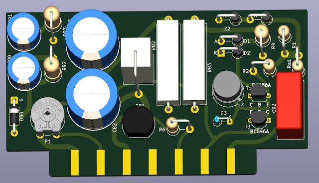
Error amp board is an open-source printed circuit board by hevanaa, from the hevanaa/Oltronix_D400 repository on GitHub. It is a 2-layer board of 92 × 51 mm with 27 parts on 20 nets, routed with 272 tracks and 0 vias.
It is built around the BZX85C12, BC546A and BC556A. Its parts include 10 resistors, 5 capacitors, 5 diodes and 2 connectors. It belongs with the audio and music and power boards of this library.


This repository contains a redesigned regulator board for the Oltronix D400-007D 400 V DC power supply.
The goal of this redesign is improved safety margins, better component availability, and improved PCB high-voltage layout compared to the original design.
/project/
KiCad PCB and schematic files
/production/
Gerber files, drill files
/docs/
Documentation, and reference material
/bom/
Bill of Materials (CSV / spreadsheet format)
This board replaces the original regulator / error amplifier section of the power supply.
Key improvements include:
The original design used a single-sided PCB edge connector layout, resulting in insufficient clearance between high-voltage pins (notably 220 V AC input and ~320–360 V DC rail).
This redesign uses a double-sided alternating pad layout, where connector contacts are split between top and bottom layers.
This achieves:
Pad geometry was also adjusted to better match connector cavity dimensions.
This project follows the original Oltronix reference designators where possible.
When deviations from the original design exist, they are documented in the schematic notes.
P1 must be adjusted during commissioning as described in the accompanying blog article: https://baldpenguin.blogspot.com/2026/04/another-oltronix-power-supply-d400-007d.html
Detailed design rationale, repair notes, and BOM information are documented in accompanying articles:
Part 1 (design analysis and failure modes):
https://baldpenguin.blogspot.com/2026/04/another-oltronix-power-supply-d400-007d.html
Part 2 (repair implementation and BOM details):
https://baldpenguin.blogspot.com/2026/06/repairing-oltronix-d400-007d-part-2.html
Part 2 contains practical component substitutions and ordering examples.
This repository contains a redesigned replacement for the regulator board used in the Oltronix D400-007D power supply.
The original device and schematic are the property of their respective rights holders and are not included under this license.
This project covers only the original work created in this repository, including the PCB layout, modified schematic, BOM, and documentation.
This project is licensed under the CERN-OHL-S v2 (Strongly Reciprocal).
See LICENSE file for details.
| Qty | Value | Footprint | References |
|---|---|---|---|
| 2 | 100k | Resistor_THT:R_Axial_DIN0516_L15.5mm_D5.0mm_P5.08mm_Vertical | R92, R93 |
| 2 | 220k | Resistor_THT:R_Axial_DIN0411_L9.9mm_D3.6mm_P5.08mm_Vertical | R2, Ra1 |
| 2 | 22µF | Capacitor_THT:CP_Radial_D16.0mm_P7.50mm | C82, C83 |
| 2 | 22µF | Capacitor_THT:CP_Radial_D10.0mm_P5.00mm | C90, C91 |
| 2 | 9k | johanh-footprints:R_Axial_Power_L25.4mm_W7mm_P27.94mm | R82, R83 |
| 2 | BZX85C12 | Diode_THT:D_DO-41_SOD81_P5.08mm_Vertical_AnodeUp | Z1, Z2 |
| 1 | 0.22 µF | Capacitor_THT:C_Rect_L18.0mm_W8.0mm_P15.00mm_FKS3_FKP3 | C92 |
| 1 | 15k | Resistor_THT:R_Axial_DIN0411_L9.9mm_D3.6mm_P5.08mm_Vertical | R1 |
| 1 | 1N4007 | Diode_THT:D_DO-41_SOD81_P5.08mm_Vertical_AnodeUp | D1 |
| 1 | 1N4007 | Diode_THT:D_DO-41_SOD81_P5.08mm_Vertical_CathodeUp | D2 |
| 1 | 1N4007 | Diode_THT:D_DO-41_SOD81_P10.16mm_Horizontal | D90 |
| 1 | 1N4148 | Diode_THT:D_DO-35_SOD27_P3.81mm_Vertical_CathodeUp | D3 |
| 1 | 1k | Resistor_THT:R_Axial_DIN0414_L11.9mm_D4.5mm_P5.08mm_Vertical | R4 |
| 1 | 1k | Potentiometer_THT:Potentiometer_Piher_PT-10-V10_Vertical | P1 |
| 1 | 2.2M | Resistor_THT:R_Axial_DIN0411_L9.9mm_D3.6mm_P5.08mm_Vertical | R6 |
| 1 | 2N4037 | Package_TO_SOT_THT:TO-39-3 | T2 |
| 1 | 3k | Resistor_THT:R_Axial_Power_L25.0mm_W9.0mm_P7.62mm_Vertical | R5 |
| 1 | BC546A | Package_TO_SOT_THT:TO-92_Inline_Wide | T3 |
| 1 | BC556A | Package_TO_SOT_THT:TO-92_Inline_Wide | T1 |
| 1 | Edge connector | johanh-footprints:Oltronix_HV_board_edge_connector_15 | J1 |
| 1 | W10G | Diode_THT:Diode_Bridge_Round_D9.8mm | D81 |
CCHS-Melbourne/vend-matrix
This is the CCHS Vending Machine motor controller.

Jajaho/Bosch-Dremel-GAL-1215-CV-repair
Reverse engineered schematics for PCB1857V1 of a Dremel 12 V battery charger.

AlexAsplund/vanchor-pcb
95×92 mm 2-layer board. Full H-bridge for a 12–24 V brushed trolling motor, controlled by the vanchor-helm board over one straight 8-wire cable. Two build variants share the same PCB:

Bihyungbetter/exoskeleton
Exoskeleton is a powered lower-limb exoskeleton with six actuated joints — hip flexion, hip abduction, and knee flexion per leg.

CatalinSerafimescu/CapacitorDischarger
A professional, handheld capacitor discharger designed for safely discharging high-voltage capacitors in hobby electronics restoration — tube amplifiers, vintage radios, CRT televisions, and consumer power supplies.


hackclub/OnBoard
💡 Join 1,000 teenagers and make your first PCB with a $100 grant!
It measures 92 × 51 mm and has 2 copper layers, 1.6 mm thick.
27 parts, built around the BZX85C12, BC546A and BC556A. The full list of its parts is on this page, with links to each part's symbol and footprint where PCBKit's library has them.
From the hevanaa/Oltronix_D400 repository on GitHub, at the commit this page was made from: the board is project/Error_amp_board.kicad_pcb and its schematic project/Error_amp_board.kicad_sch. PCBKit opens the board in the browser, with nothing to install.
Its repository states no licence, so its author keeps all rights: ask hevanaa before reusing the design.