

4 layers180.3 × 114.9 mm

This is my first electronic project, it was inspired by this video (https://www.youtube.com/watch?v=EbNv-qJeaCI). I follow most of his premise, but use it to create the schema, the PCB and a functional prototype.
Dice is an open-source printed circuit board by HereticMontano, from the HereticMontano/PCBDice repository on GitHub. It is a 2-layer board of 81.6 × 48.2 mm with 28 parts on 33 nets, routed with 148 tracks and 4 vias.
It is built around the 74LS32SC. Its parts include 12 resistors, 8 diodes, 3 ICs, 2 switches and 1 capacitor.
This is my first electronic project, it was inspired by this video (https://www.youtube.com/watch?v=EbNv-qJeaCI). I follow most of his premise, but use it to create the schema, the PCB and a functional prototype.
Create a virtual 6 faces dice. When push the button, it fire the clock to send an astable signal to the IC counter from 1 to 7 (the 7 it will restar the counter).
It can handle the 6 posible state, only managmente 4 groups of leds.
*2     *5
*3  *1 *6
*4     *7
Learn how to use KICad and how to make a schema, and some of good practice/convention to do it. I had to re do a cuple of time to improve the readability of it, in the first version the lines are all over the place.
Learn to solder and use bigger PCB board next time. Using this small PCB to following the conection from on leg to another was a nighmare, and have no room to add the resitance in his respective holes.
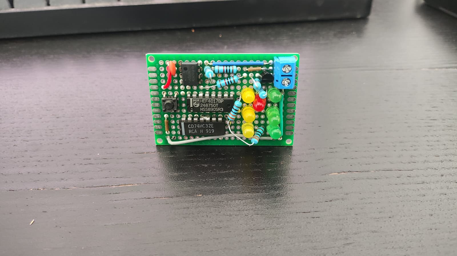
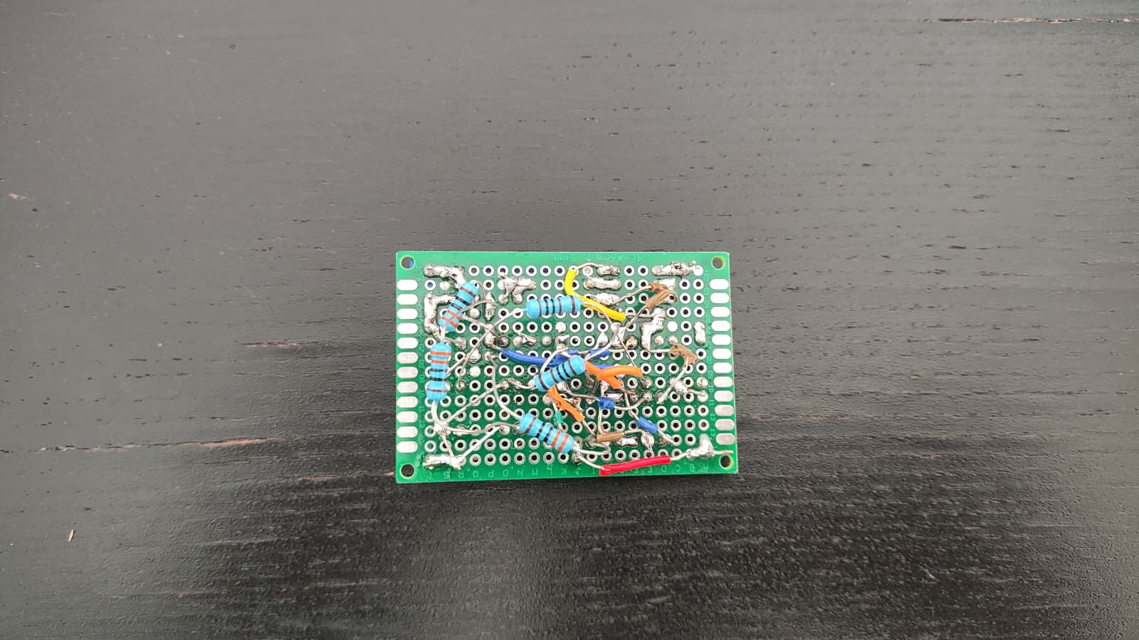
Keep learning KiCad and how to use the PCB Editor, managment the footprint of the diferente components
| Qty | Value | Footprint | References |
|---|---|---|---|
| 7 | LED | LED_THT:LED_D5.0mm | D1, D2, D3, D4, D5, D6, D7 |
| 6 | 300 | Resistor_THT:R_Axial_DIN0204_L3.6mm_D1.6mm_P5.08mm_Horizontal | R1, R2, R4, R5, R7, R12 |
| 3 | 10K | Resistor_THT:R_Axial_DIN0204_L3.6mm_D1.6mm_P5.08mm_Horizontal | R8, R9, R10 |
| 2 | 1k | Resistor_THT:R_Axial_DIN0204_L3.6mm_D1.6mm_P5.08mm_Horizontal | R3, R6 |
| 1 | 100 nF | Capacitor_THT:C_Disc_D5.0mm_W2.5mm_P2.50mm | C1 |
| 1 | 2K | Resistor_THT:R_Axial_DIN0204_L3.6mm_D1.6mm_P5.08mm_Horizontal | R11 |
| 1 | 4017 | Package_DIP:DIP-16_W7.62mm | U2 |
| 1 | 74LS32 | Package_DIP:DIP-14_W7.62mm | U3 |
| 1 | Battery_Cell | Battery:BatteryHolder_Keystone_103_1x20mm | BT1 |
| 1 | D | Diode_THT:D_DO-41_SOD81_P10.16mm_Horizontal | D8 |
| 1 | LM555xM | Package_DIP:DIP-8_W7.62mm | U1 |
| 1 | NPN | Package_TO_SOT_THT:TO-92_Inline | Q1 |
| 1 | SW_DPST_x2 | Button_Switch_THT:SW_Slide-03_Wuerth-WS-SLTV_10x2.5x6.4_P2.54mm | SW2 |
| 1 | SW_Push | Button_Switch_THT:SW_PUSH-12mm_Wuerth-430476085716 | SW1 |


jes/scamp-cpu
A homebrew 16-bit CPU with a homebrew Unix-like-ish operating system.

mudmin/AnotherMaker
This is where I will store code snippets for AnotherMaker Videos


The-Invent0r/8-bit-Computer-PCB
These are the KiCAD files for my 8-Bit Computer.

tjboldt/Apple2-IO-RPi
Apple II expansion card using a Raspberry Pi for I/O
It measures 81.6 × 48.2 mm and has 2 copper layers, 1.6 mm thick.
28 parts, built around the 74LS32SC. The full list of its parts is on this page, with links to each part's symbol and footprint where PCBKit's library has them.
From the HereticMontano/PCBDice repository on GitHub, at the commit this page was made from: the board is Dice.kicad_pcb and its schematic Dice.kicad_sch. PCBKit opens the board in the browser, with nothing to install.
Its repository states no licence, so its author keeps all rights: ask HereticMontano before reusing the design.