4 layers103 × 82.4 mm

 heimdilon/stm32f103c8t6-devboard
Custom STM32F103C8T6 development board designed in KiCad and hand-assembled as a prototype.
My stm32-devboard is an open-source printed circuit board by heimdilon, from the heimdilon/stm32f103c8t6-devboard repository on GitHub. It is a 2-layer board of 74.5 × 57.3 mm with 48 parts on 55 nets, routed with 469 tracks and 51 vias.
It is built around the STM32F103C8T6, MCP2551-I/SN-HG and AMS1117-3.3, with the USBLC6-2SC6 among its other parts. Its parts include 14 capacitors, 11 resistors, 10 connectors, 5 ICs and 2 diodes. It belongs with the microcontroller boards boards and the STM32 boards of this library.


A custom STM32F103C8T6 development board designed in KiCad and taken through the full prototype workflow: schematic capture, PCB layout, manufacturing output generation, PCB fabrication, component sourcing, hand soldering, and physical assembly.
The board was designed as a compact embedded development platform exposing common STM32 interfaces for firmware experiments, peripheral testing, and hardware bring-up practice.
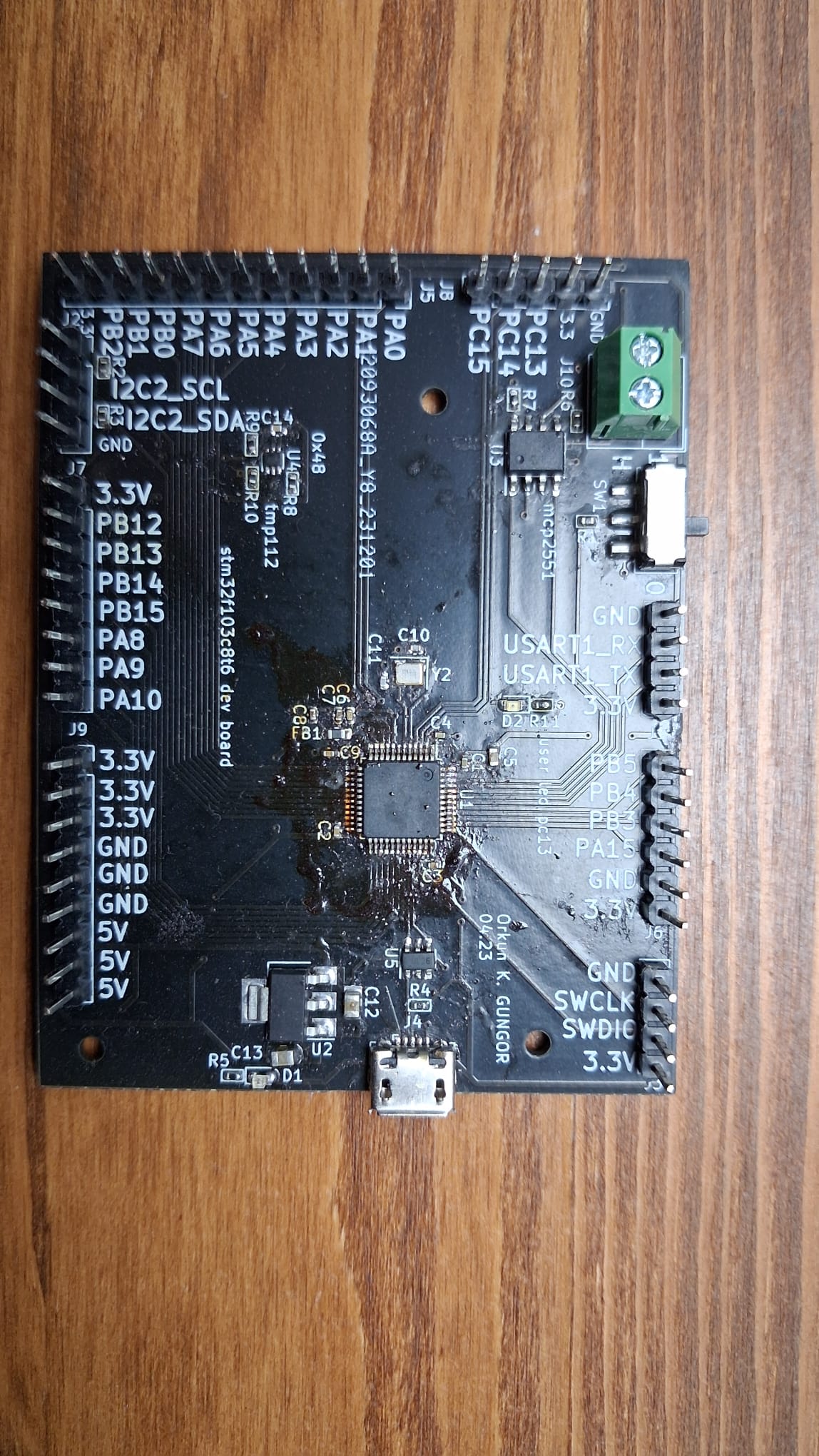
The design breaks out the STM32F103C8T6 pins to labeled headers while keeping the support circuitry needed for real board bring-up:
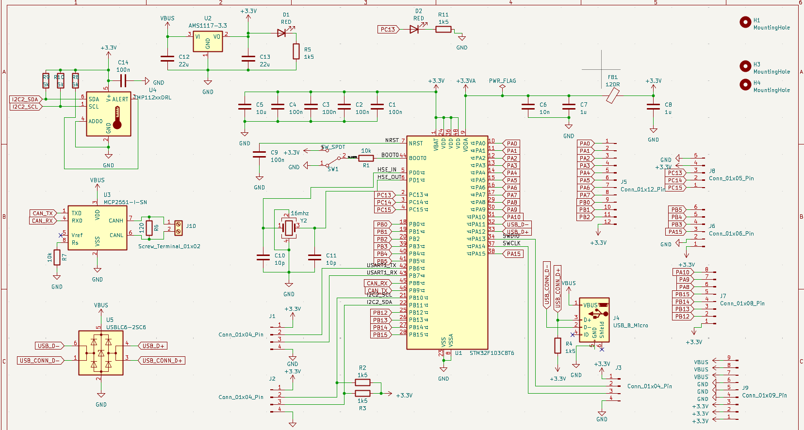
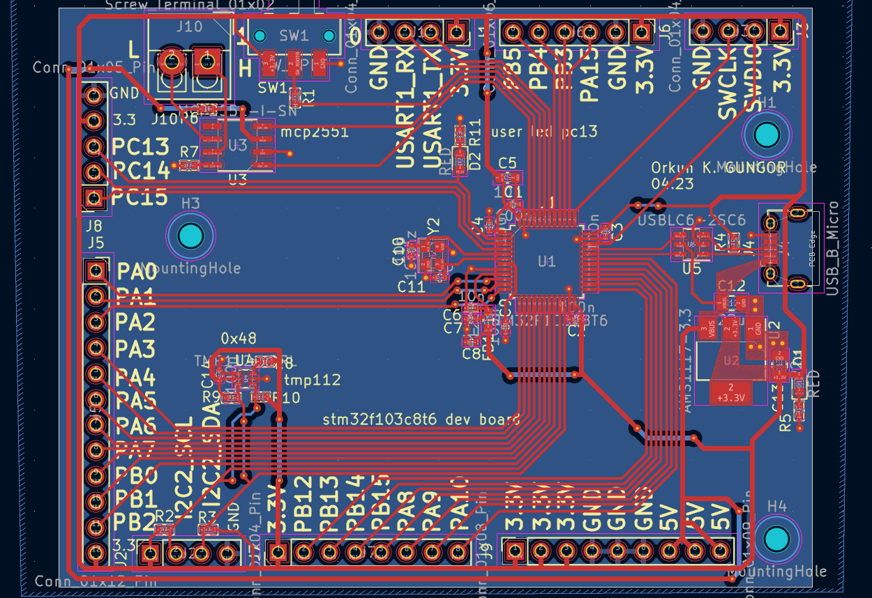
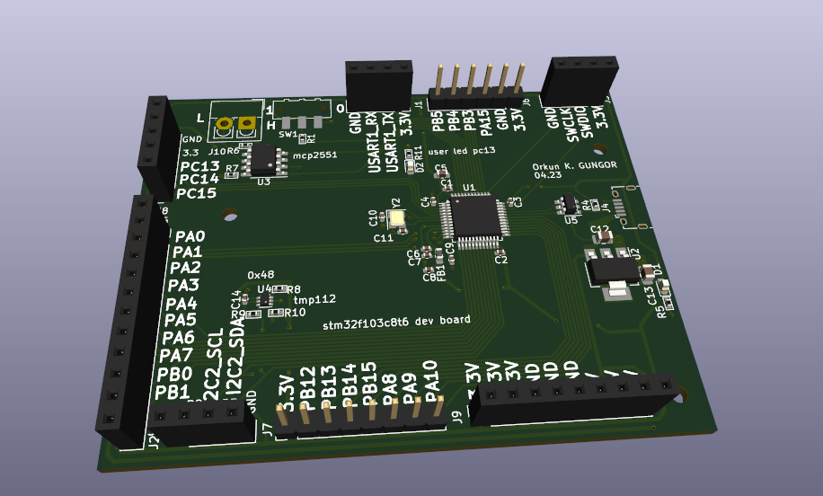
.
|-- my_stm32-devboard.kicad_pro       KiCad project file
|-- my_stm32-devboard.kicad_sch       Schematic source
|-- my_stm32-devboard.kicad_pcb       PCB layout source
|-- manufacturing/                    Gerber and drill files exported from KiCad
|-- production/                       BOM, placement, netlist, and packaged Gerber output
|-- docs/images/                      README images and assembled board photo
|-- *.STEP 3D models used by the boardDesigned and assembled by Orkun K. Gungor, 2023.
| Qty | Value | Footprint | References |
|---|---|---|---|
| 6 | 100n | Capacitor_SMD:C_0402_1005Metric | C1, C2, C3, C4, C9, C14 |
| 5 | 1k5 | PCM_Resistor_SMD_AKL:R_0402_1005Metric | R2, R3, R4, R5, R11 |
| 3 | 5k | PCM_Resistor_SMD_AKL:R_0402_1005Metric | R8, R9, R10 |
| 3 | Conn_01x04_Pin | Connector_PinSocket_2.54mm:PinSocket_1x04_P2.54mm_Vertical | J1, J2, J3 |
| 3 | MountingHole | MountingHole:MountingHole_2.2mm_M2 | H1, H3, H4 |
| 2 | 10k | PCM_Resistor_SMD_AKL:R_0402_1005Metric | R1, R7 |
| 2 | 10p | Capacitor_SMD:C_0402_1005Metric | C10, C11 |
| 2 | 1u | Capacitor_SMD:C_0402_1005Metric | C7, C8 |
| 2 | 22u | Capacitor_SMD:C_0805_2012Metric | C12, C13 |
| 2 | RED | LED_SMD:LED_0603_1608Metric | D1, D2 |
| 1 | 10n | Capacitor_SMD:C_0402_1005Metric | C6 |
| 1 | 10u | Capacitor_SMD:C_0603_1608Metric | C5 |
| 1 | 120 | PCM_Resistor_SMD_AKL:R_0402_1005Metric | R6 |
| 1 | 120R | Inductor_SMD:L_0603_1608Metric | FB1 |
| 1 | 16mhz | Crystal:Crystal_SMD_2520-4Pin_2.5x2.0mm | Y2 |
| 1 | AMS1117-3.3 | Package_TO_SOT_SMD:SOT-223-3_TabPin2 | U2 |
| 1 | Conn_01x05_Pin | Connector_PinSocket_2.54mm:PinSocket_1x05_P2.54mm_Vertical | J8 |
| 1 | Conn_01x06_Pin | Connector_PinHeader_2.54mm:PinHeader_1x06_P2.54mm_Vertical | J6 |
| 1 | Conn_01x08_Pin | Connector_PinHeader_2.54mm:PinHeader_1x08_P2.54mm_Vertical | J7 |
| 1 | Conn_01x09_Pin | Connector_PinSocket_2.54mm:PinSocket_1x09_P2.54mm_Vertical | J9 |
| 1 | Conn_01x12_Pin | Connector_PinSocket_2.54mm:PinSocket_1x12_P2.54mm_Vertical | J5 |
| 1 | MCP2551-I-SN | Package_SO:SOIC-8_3.9x4.9mm_P1.27mm | U3 |
| 1 | STM32F103C8T6 | Package_QFP:LQFP-48_7x7mm_P0.5mm | U1 |
| 1 | SW_SPDT | Button_Switch_SMD:SW_SPDT_CK-JS102011SAQN | SW1 |
| 1 | Screw_Terminal_01x02 | TerminalBlock_4Ucon:TerminalBlock_4Ucon_1x02_P3.50mm_Vertical | J10 |
| 1 | TMP112xxDRL | Package_TO_SOT_SMD:SOT-563 | U4 |
| 1 | USBLC6-2SC6 | Package_TO_SOT_SMD:SOT-23-6 | U5 |
| 1 | USB_B_Micro | Connector_USB:USB_Micro-B_Amphenol_10118194_Horizontal | J4 |
It measures 74.5 × 57.3 mm and has 2 copper layers, 1.6 mm thick.
48 parts, built around the STM32F103C8T6, MCP2551-I/SN-HG, AMS1117-3.3 and USBLC6-2SC6. The full list of its parts is on this page, with links to each part's symbol and footprint where PCBKit's library has them.
From the heimdilon/stm32f103c8t6-devboard repository on GitHub, at the commit this page was made from: the board is my_stm32-devboard.kicad_pcb and its schematic my_stm32-devboard.kicad_sch. PCBKit opens the board in the browser, with nothing to install.
Its repository states no licence, so its author keeps all rights: ask heimdilon before reusing the design.

SurajSonawane2415/PCB-Design-STM32-Dev-Board
Custom STM32 Development (PCB) Board with an on-board SPI sensor (TC72).


Adityasc9/STM32-Custom-PCB
Hardware design files for a custom STM32 development board created in KiCad.


Ferid10/STM32F103C8T6-design
my pcb design where i made a stm 32 board with temprature and pressure sensor using both spi and i2c communication

stevenwdyer/stm32f1-dev-board
A compact, custom development PCB for an STM32F1 microcontroller
