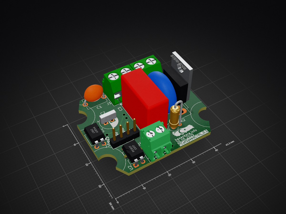
PCutSpeedCTRL Constant Speed Controller
- It provides constant speed operation and remote control of single phase AC motor suitable for operation with 220 vac 50hz.
- When produced with BTA41 triac switching element, it provides usage up to 40 Ampere. In my initial tests I used a 1.2kW AC motor.
- The first version component cost was calculated as $3,075.
- Suitable for use with standard hand milling motors that are easily available on the world market.
- The mentioned milling motors are suitable for use in CNC machines.
- Any CNC controller can be connected directly and in isolation with a standard PWM output.
- This resource contains design and production files for hardware and firmware.
- PC Software used in the development process; KICAD 9 for Hardware, MOUNRIVER 2.1 IDE and C programming language were used for Firmware. OCTAVE was used to create look up tables for some mathematical equations.
- Test Video Youtube Link
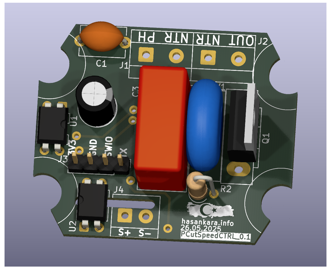 | 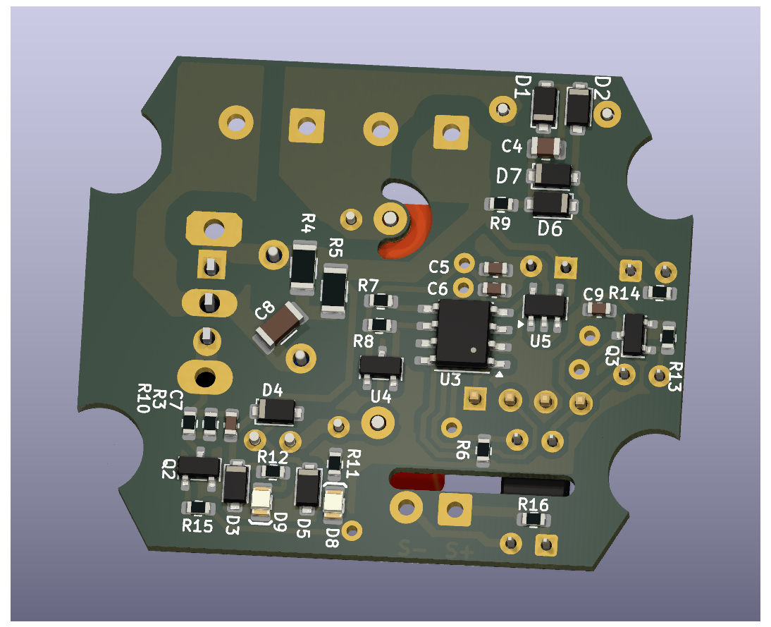 |
| 3D Front | 3D Rear |
HARDWARE Detail:
Schematic Detail:
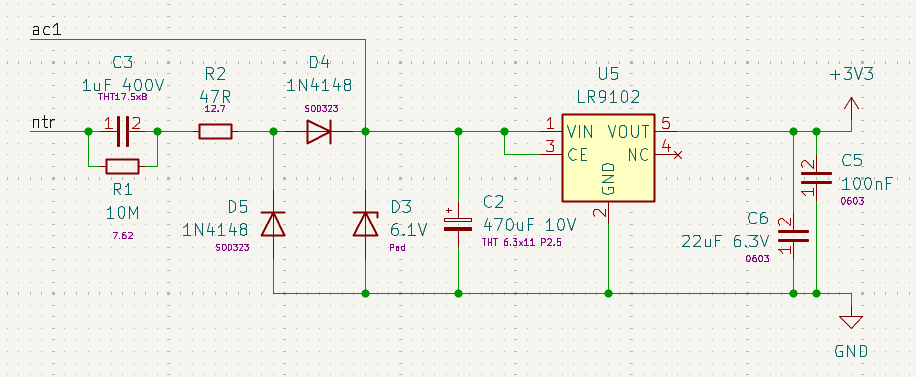 |
Non Isolated Power Supply:
- A cost-effective, non-isolated design was implemented for low voltage supply needs.
- This scheme can meet the required 30mA power requirement. This power is mainly used for MCU operation, hall effect sensor operation and TRIAC triggering.
|
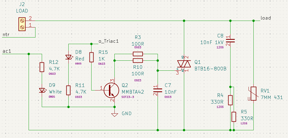 |
Triac gate drive circuit:
- Phase cut topology used.
- Some snubber components applied.
|
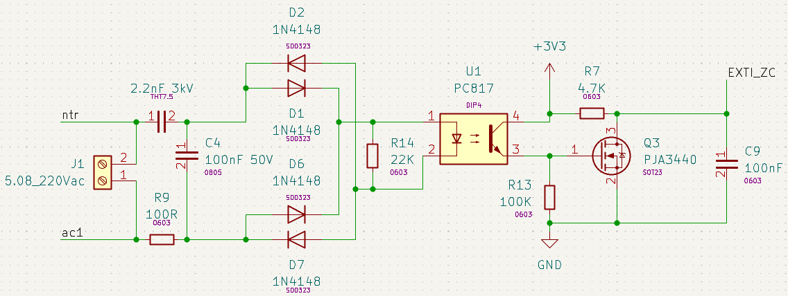 |
Zero cross detection circuit:
- With q3 mosfet, a faster falling edge signal is generated.
|
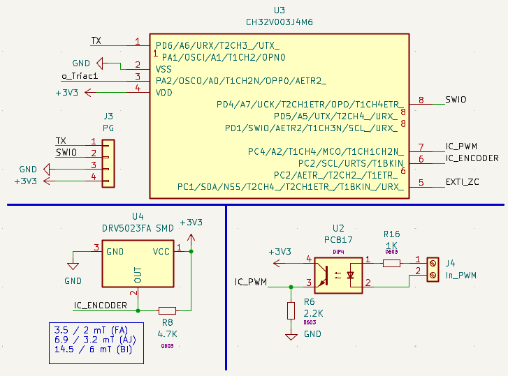 |
MCU, Hall Sensor and PWM Input Circuit:
- It was developed using the ch32v003j4m6 microcontroller from wch company.
- DRV5023 hall sensor was used for spindle speed measurement.
|
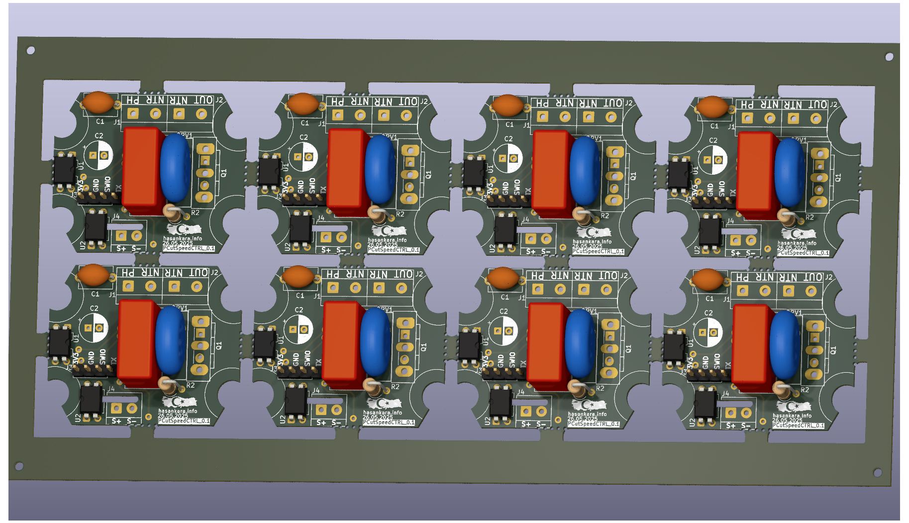
Panelize Detail:
- We use the Kikit plugin for PCB paneling.
- We can panelize the PCB design by running the panelize_multiple.py file located in the "/HW/Panelize/" file path.
- Phase cut topology used.
- In panelized form, a new kicad project is created automatically.
 | 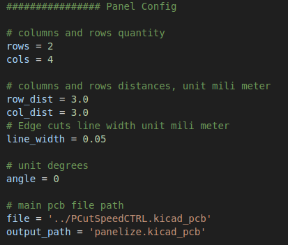 |
| Panelize Wiew | Some Panel Settings in panelize_multiple.py |
Mechanic Detail:
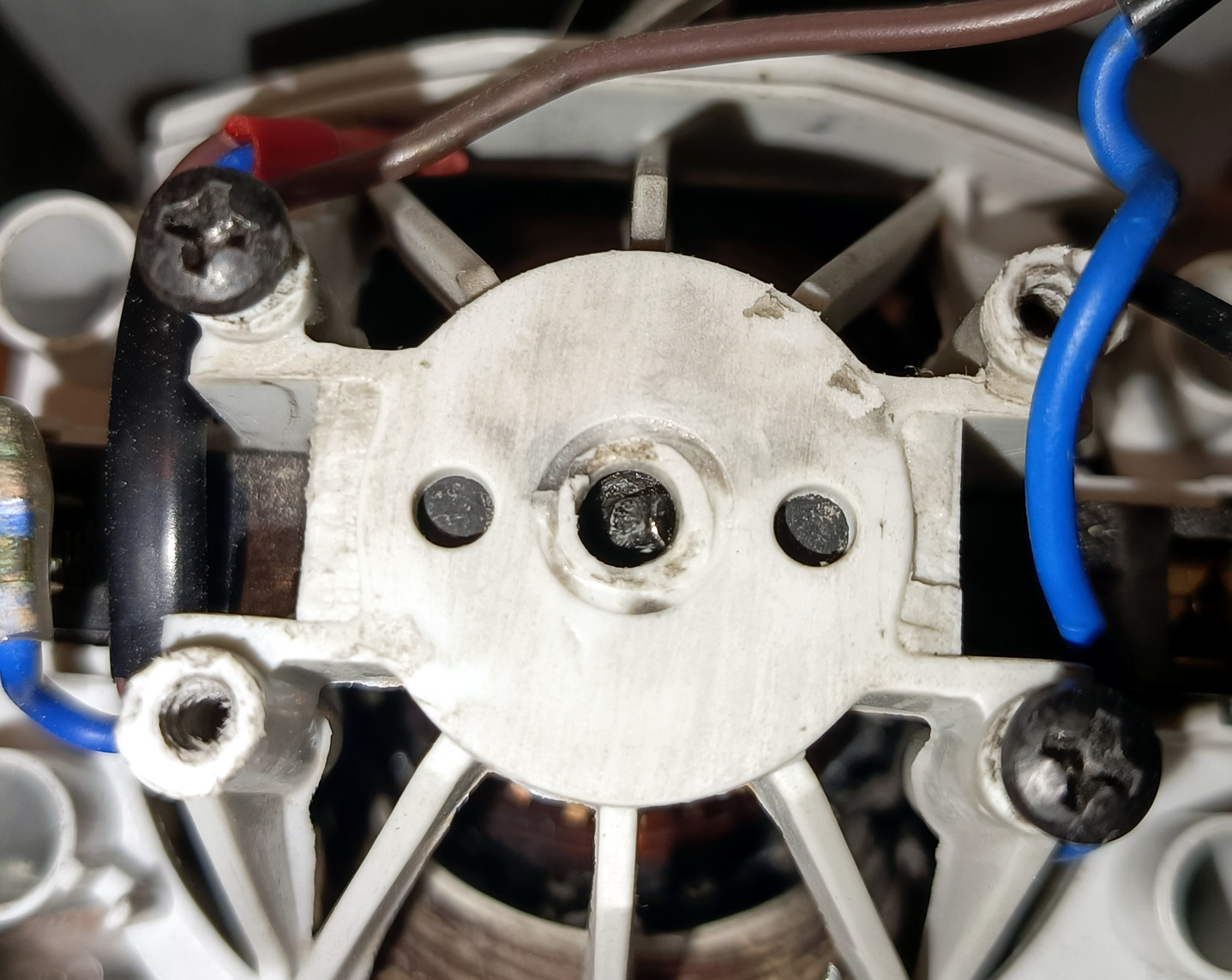
- When the AC motor top cover is opened, 4 screw holes can be seen.
- When the top cover of the spindle motor is first opened, there will be no hole in the middle
- A metric 5 diameter hole should be drilled along the shaft, coinciding with the center.
- While designing the PCB, compatibility was ensured by using the Mac Allister manufacturer MSR1200 model AC motor.
 |
-
A 3x3 mm cylindrical neodymium magnet is inserted through this hole and coupled with the shaft.
- There should be an angle of approximately ~45° between the magnet cylinder center axis and the shaft axis.
- The shaft and magnet can be attached using super glue.
|
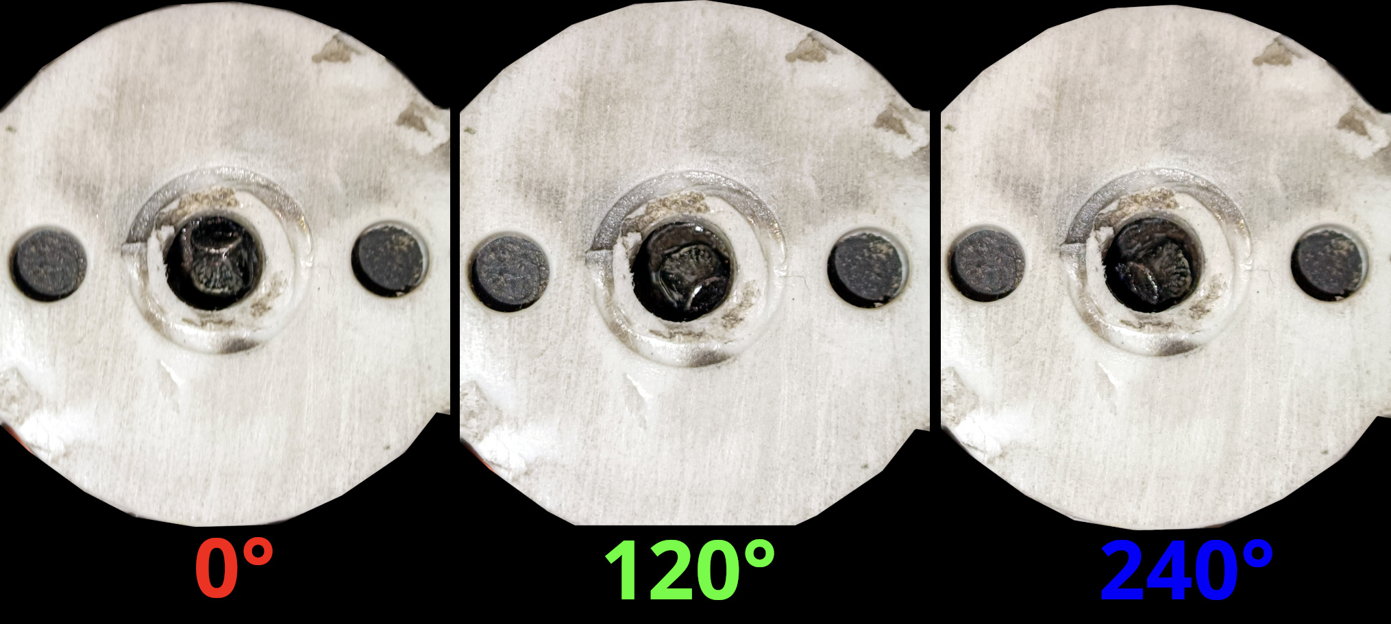
When the rotor is turned to different angles, it should be confirmed that the magnet rotates together.
|
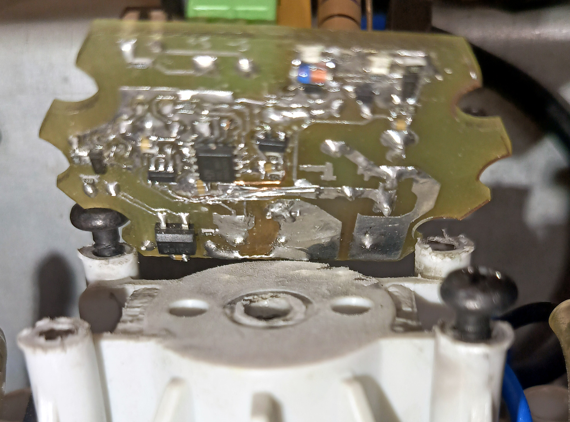
Spindle Motor Controller assembly demonstration
|
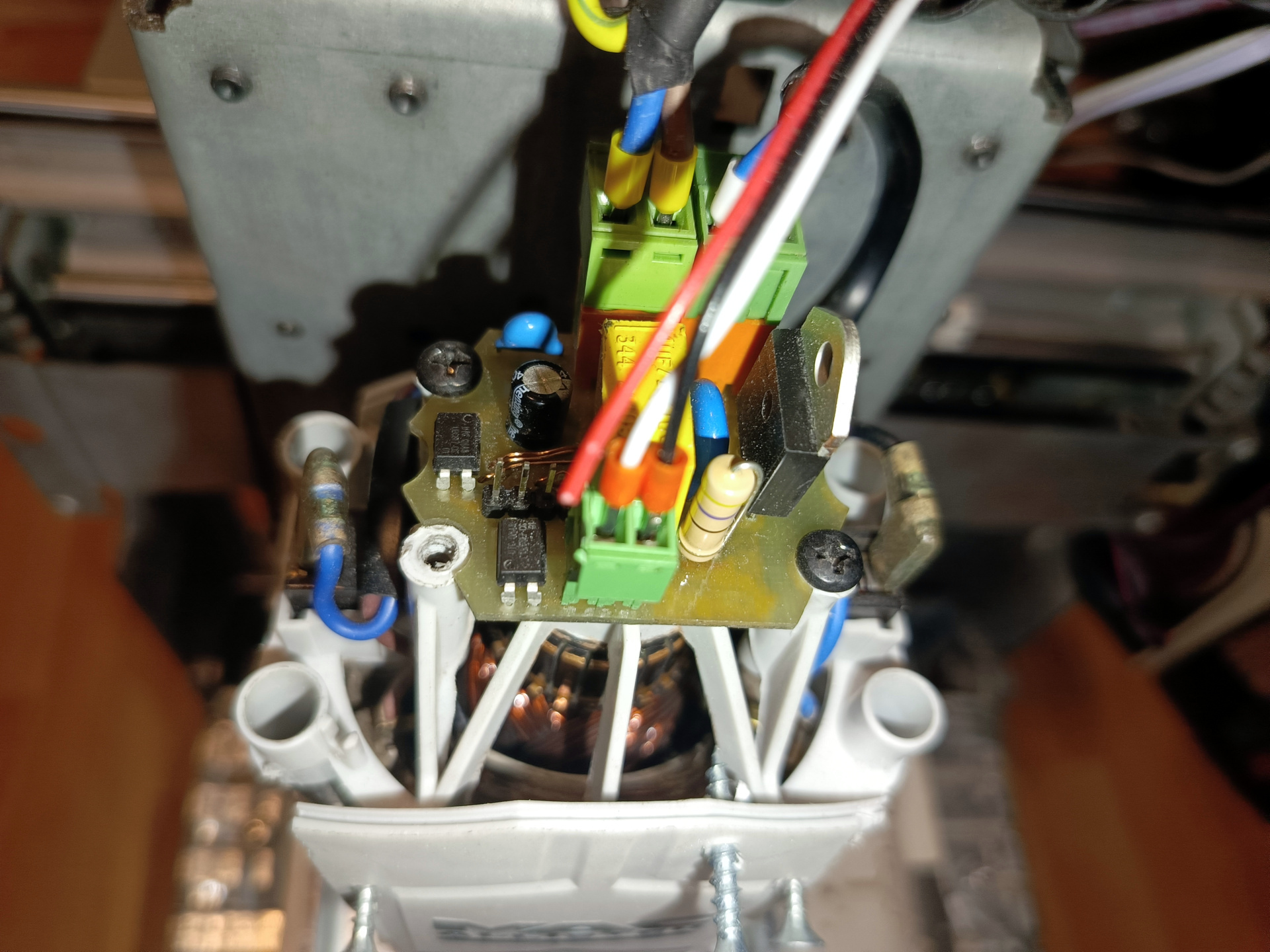
Spindle Motor Controller Driver Applied
|
Firmware Detail:
- MOUNRIVER 2.1 IDE and C programming language were used for Firmware.
- The HYB cooperative operating system was used for the MCU resource management organization.
- Since the cooperative real-time operating system we use is very lightweight, it can easily adapt to the Microcontroller despite its weak memory.
- With this project, I am also sharing the cooperative operating system that I have been developing over the years as open source.
- I also added some libraries to the firmware that are not actively in use but could enable developments that fit the structure of the project.
- NTC temperature sensor data interpretation, ADC reading, moving average filter, some of them.
About the main routine:
- Using 2 different input capture modules, PWM input data was taken with IC1 and the magnetic sensor digital output frequency value was measured with IC2.
- Speed change commands have been smoothed to create a ramp between the PWM data and the target speed information.
- Zero Cross detection was performed using the external interrupt module. Triac triggering and PID routines were run with each ZC detection.
- For linearization of the system, the source signal is assumed to be a sinusoidal signal. The equation used is the integral of the half sine signal.
- For system linearization, PID output information was applied to the linearization function using the look up table interpolation created with the Octave PC application.
- Thus, a more stable closed-loop system was obtained with fixed PID coefficients.
- Duty data was evaluated as time data to convert it into TRIAC switch signal.
- In addition to the look up table, a firmware setting option has been added to enable linearization by measurement method.
- The firmware can be made to work with different features with a set of predefined settings.
- The mentioned settings can be seen in the image below, as well as in the main.c file.
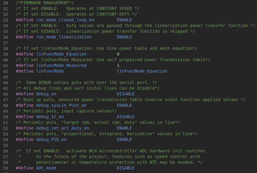
Firmware Managment Settings 1
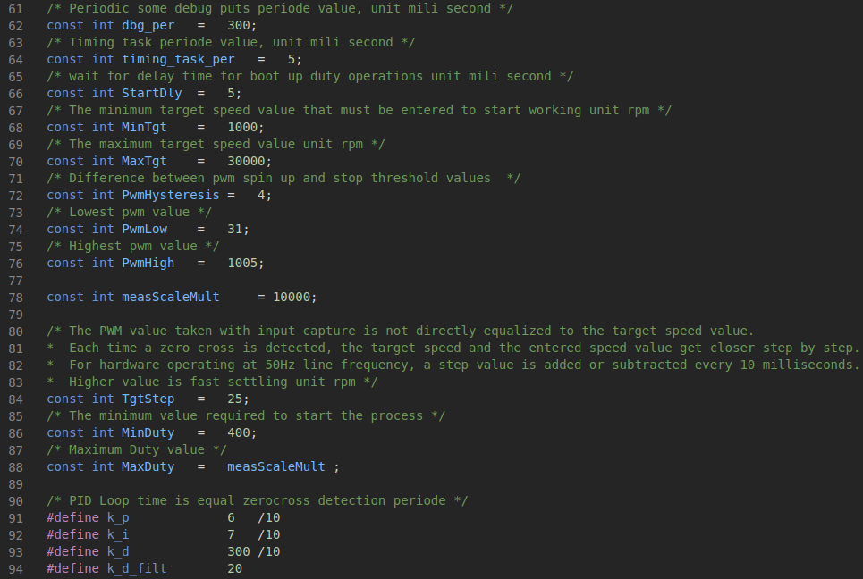
Firmware Managment Settings 2
Octave Equations Plot and Print :
- The linearization table created with Octave PC software can be examined graphically and can be evaluated by copying and pasting directly into the C code.
- Similarly, the linearization table output from the MCU serial port output at boot up time can be directly copied and pasted into the Octave software and visually inspected.
|
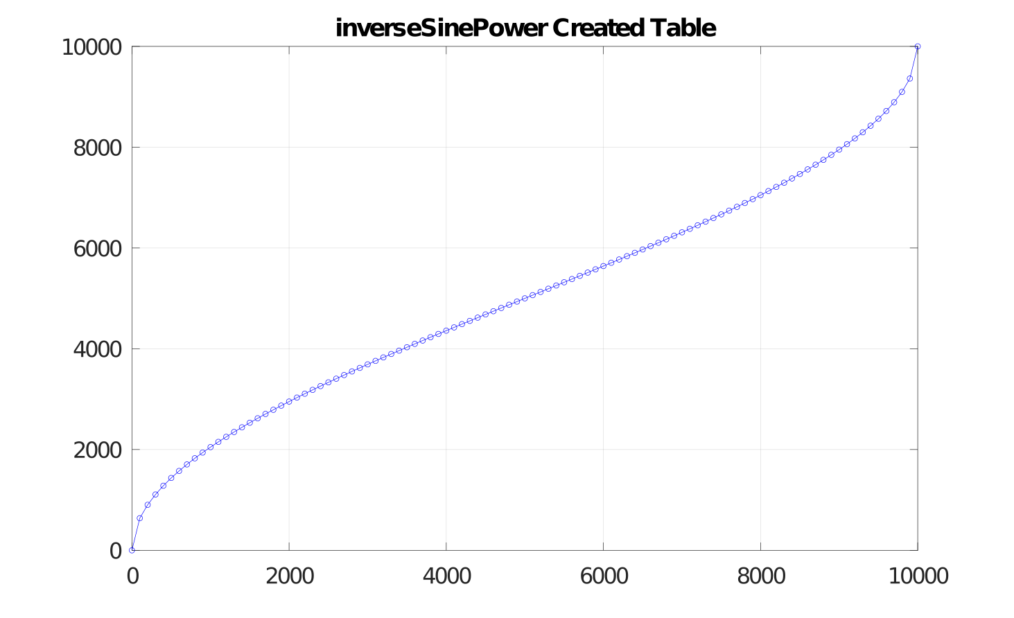
Inverse Sine Power Equation Created
|
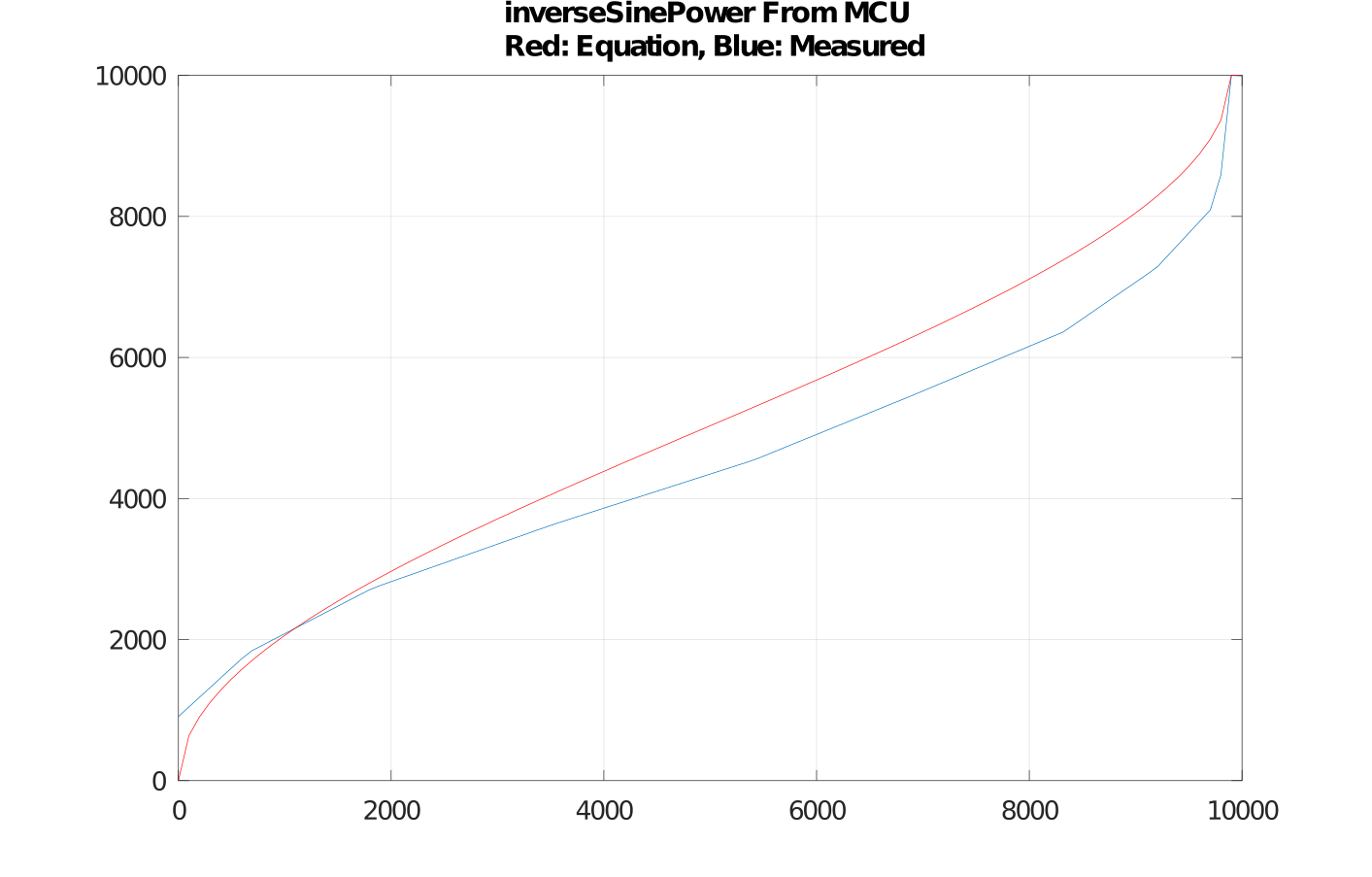
Inverse Sine Power from MCU, Equation and Measured
|
Some Tests:
- As can be watched in the video link shared above, we performed some aluminum sheet and PCB drilling tests.
- When we apply sudden strain and sudden release tests, overshooting values of up to 800 rpm occur.
- The spindle motor we tested has a 30k rpm feature at full power.
- As is known, keeping a constant speed at low rotational speeds can be a very challenging goal.
- Its ability to remain at low overshoot values while at 1k rmp target speed is at a satisfactory level.
- We could observe that it does not work so stably unless linearization is applied.
- We made it possible to observe the result by disabling a single predefined setting via the firmware.
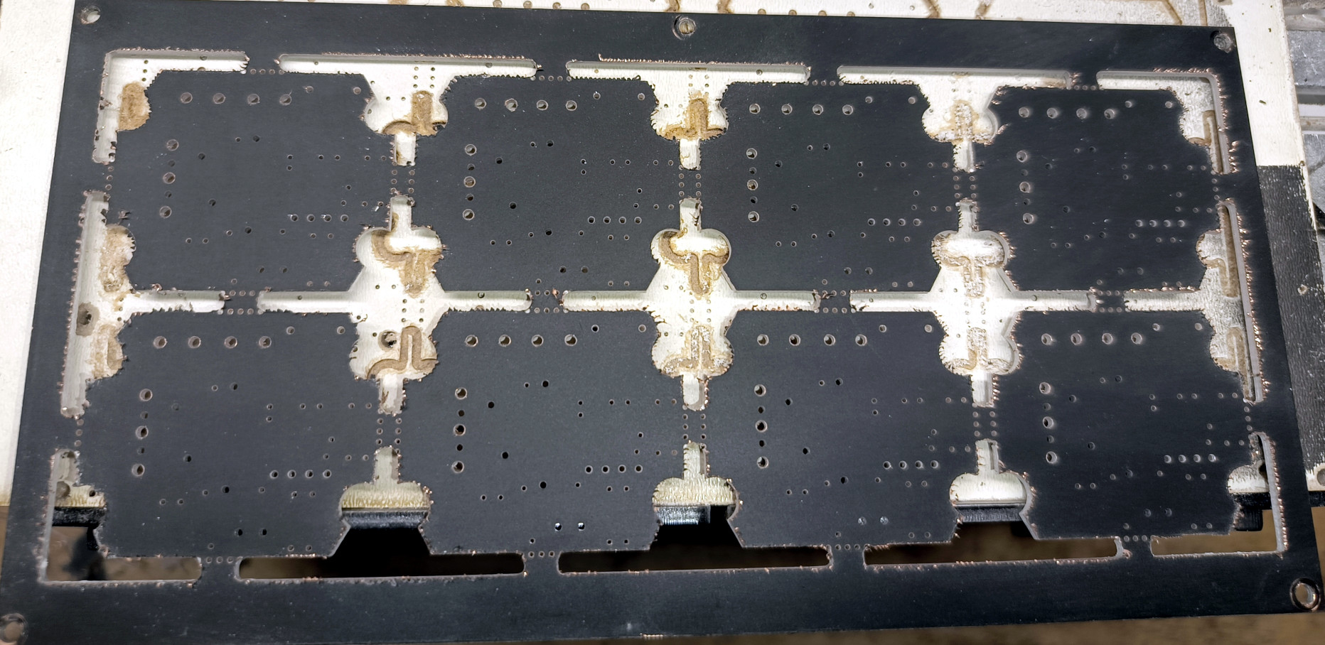
PCB Milling and Edge Cut Test Front
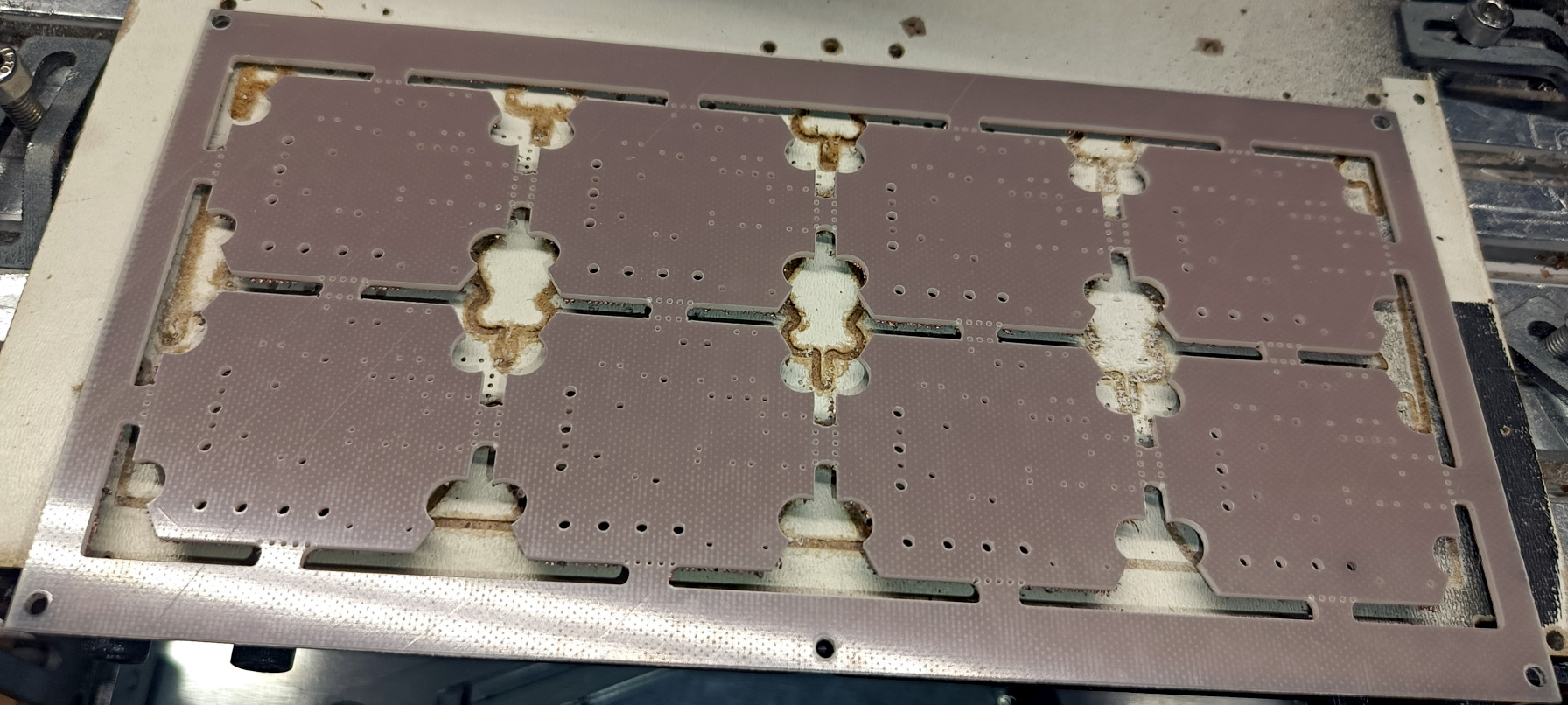
PCB Milling and Edge Cut Test Rear
Production:
- Gcode files created for PCB production with DIY techniques can be found in the HW/Panelize/Plot_diy folder.
- The bom list, along with supply links and unit prices, can be viewed in the "HW/bom" file path.
- For PCB fabrication files, files in the "HW/Plot" or "HW/Panelize/Plot" file path can be compressed and shared directly with the PCB manufacturer.