



4 layers149 × 95 mm
 Hang020713/GPIO_Control_Circuit
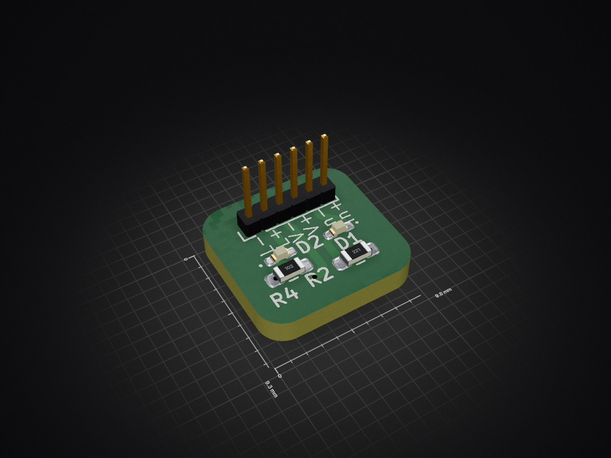
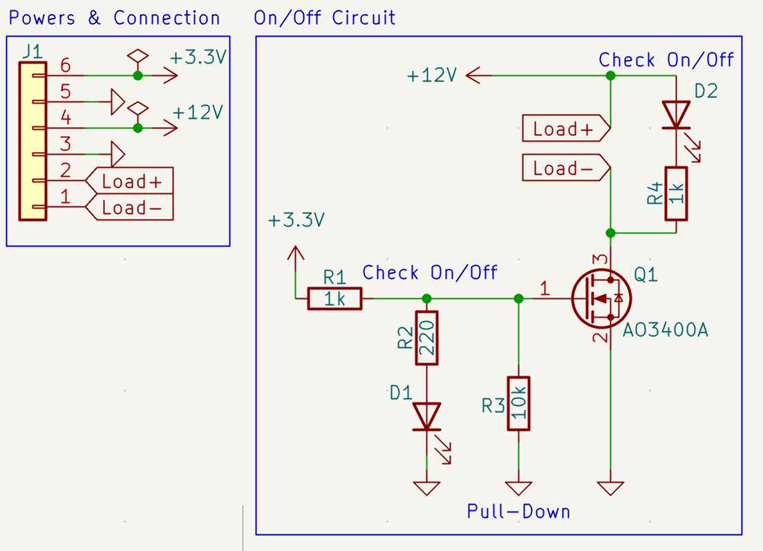
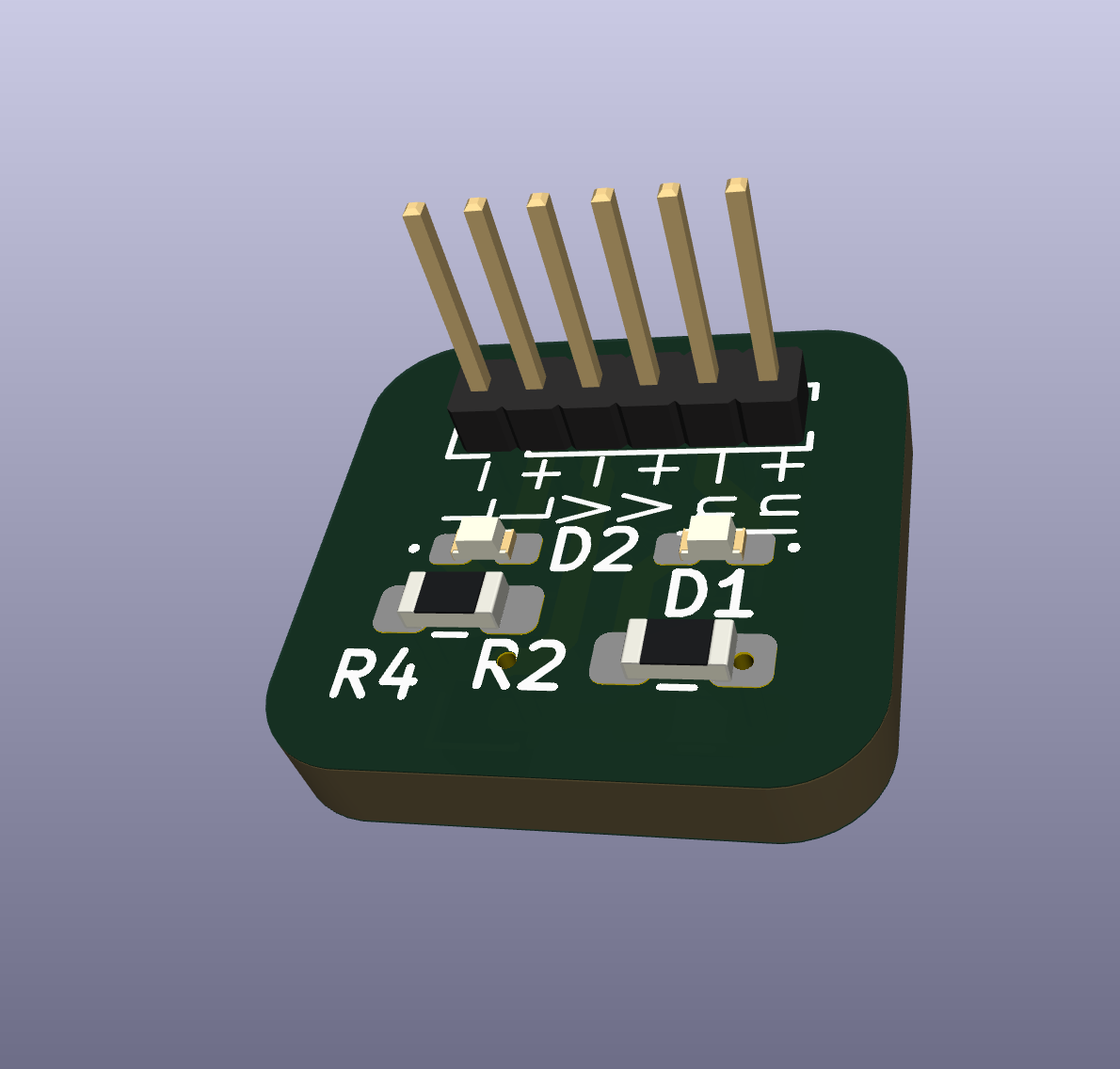
This is a pcb with GPIO input to on and off the load device
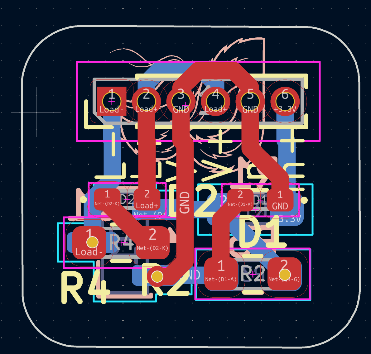
GPIO Control Circuit is an open-source printed circuit board by Hang020713, from the Hang020713/GPIO_Control_Circuit repository on GitHub. It is a 2-layer board of 9.8 × 9.3 mm with 9 parts on 7 nets, routed with 43 tracks and 3 vias.
It is built around the AO3400A. Its parts include 4 resistors, 2 diodes, 1 transistor and 1 connector.
[blocked]
This is a pcb with GPIO input to on and off the load device
├── USB-C-Regulator.kicad_pcb   # PCB Layout
├── USB-C-Regulator.kicad_pro   # KiCad Project File
├── USB-C-Regulator.kicad_sch   # Schematic
└── README.mdkicad_pcb - PCB Layoutkicad_sch - Schematickicad_pro - KiCad Project Configuration FileRequirements
Open the .kicad_pro file using KiCad 8 to access the full project including schematic and PCB layout.
This PCB have below features
⚠️ Always verify output voltage before powering sensitive electronics.
| Reference | Value | Package / Footprint | Qty |
|---|---|---|---|
| D1, D2 | LED | LED_0402_1005Metric | 2 |
| J1 | Conn_01x06 | PinHeader_1x06_P1.00mm_Vertical | 1 |
| Q1 | AO3400A | SOT-23 | 1 |
| R1, R4 | 1kΩ | R_0603_1608Metric | 2 |
| R2 | 220Ω | R_0603_1608Metric | 1 |
| R3 | 10kΩ | R_0603_1608Metric | 1 |
MIT License
Feel free to use, modify, and distribute.
I'm always interested in collaborating on embedded systems projects, robotics competitions, or autonomous vehicle development!
| Qty | Value | Footprint | References |
|---|---|---|---|
| 2 | 1k | Resistor_SMD:R_0603_1608Metric_Pad0.98x0.95mm_HandSolder | R1, R4 |
| 2 | LED | LED_SMD:LED_0402_1005Metric_Pad0.77x0.64mm_HandSolder | D1, D2 |
| 1 | 10k | Resistor_SMD:R_0603_1608Metric_Pad0.98x0.95mm_HandSolder | R3 |
| 1 | 220 | Resistor_SMD:R_0603_1608Metric_Pad0.98x0.95mm_HandSolder | R2 |
| 1 | AO3400A | Package_TO_SOT_SMD:SOT-23 | Q1 |
| 1 | Conn_01x06 | Connector_PinHeader_1.00mm:PinHeader_1x06_P1.00mm_Vertical | J1 |
| 1 | LOGO | LOGO | G*** |


brickbots/PiFinder
A plate solving telescope finder based around a Raspberry PI and RPI HQ Camera


MickiusMousius/Rolio46Keyboard
A split wireless keyboard based on the Corne and Sofle
It measures 9.8 × 9.3 mm and has 2 copper layers, 1.6 mm thick.
9 parts, built around the AO3400A. The full list of its parts is on this page, with links to each part's symbol and footprint where PCBKit's library has them.
From the Hang020713/GPIO_Control_Circuit repository on GitHub, at the commit this page was made from: the board is GPIO_Control_Circuit.kicad_pcb and its schematic GPIO_Control_Circuit.kicad_sch. PCBKit opens the board in the browser, with nothing to install.
Its repository states no licence, so its author keeps all rights: ask Hang020713 before reusing the design.