4 layers160.7 × 51.7 mm
 hamzadenizyilmaz/BoostCore-Module
1.5V–28V DC-DC Step-Up Boost Converter Module
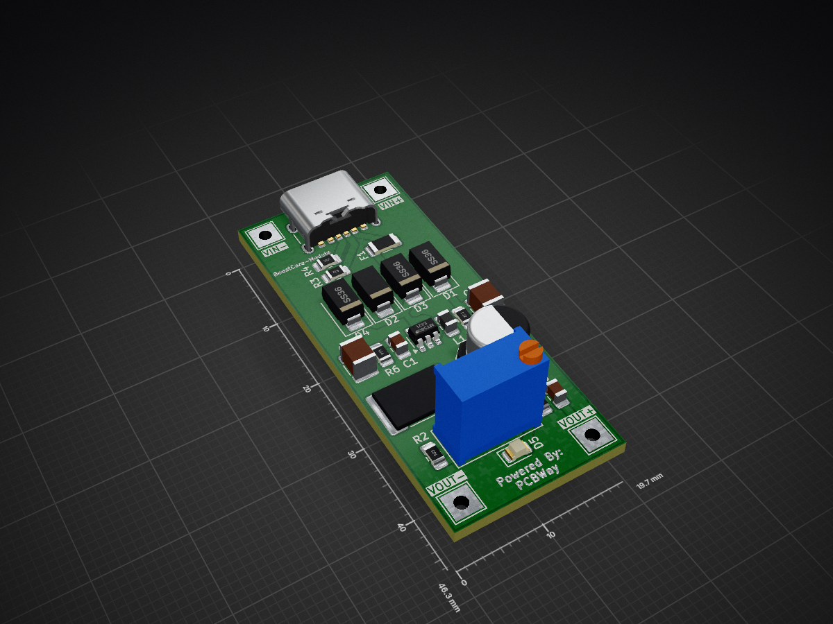
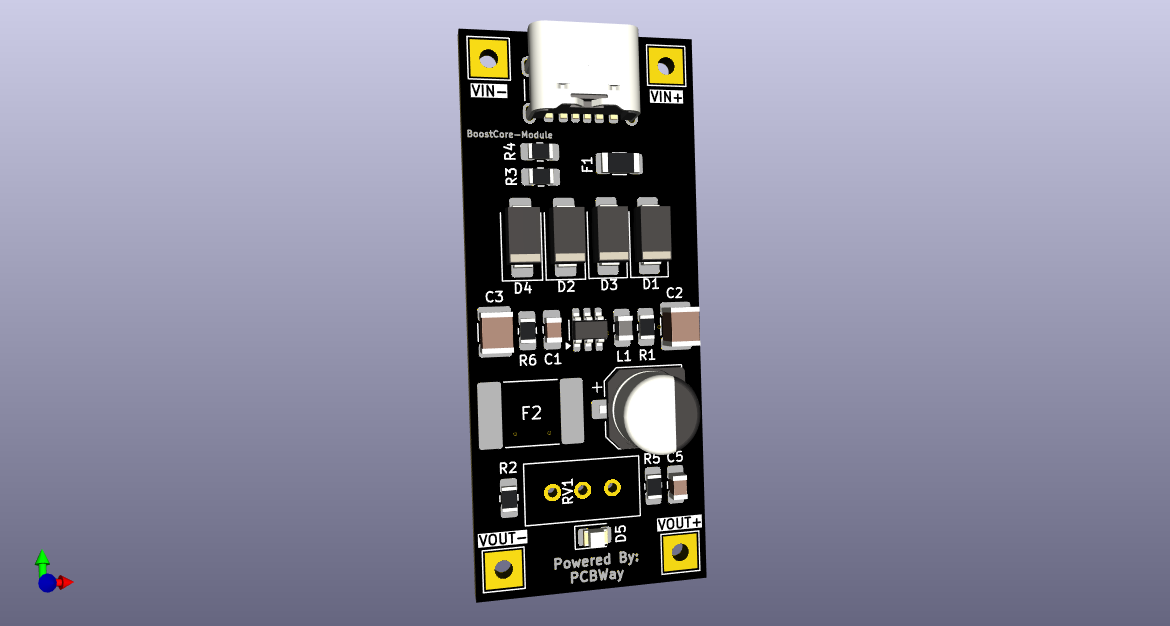
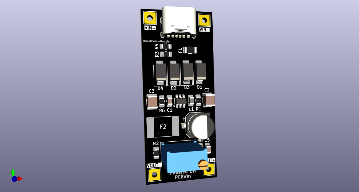
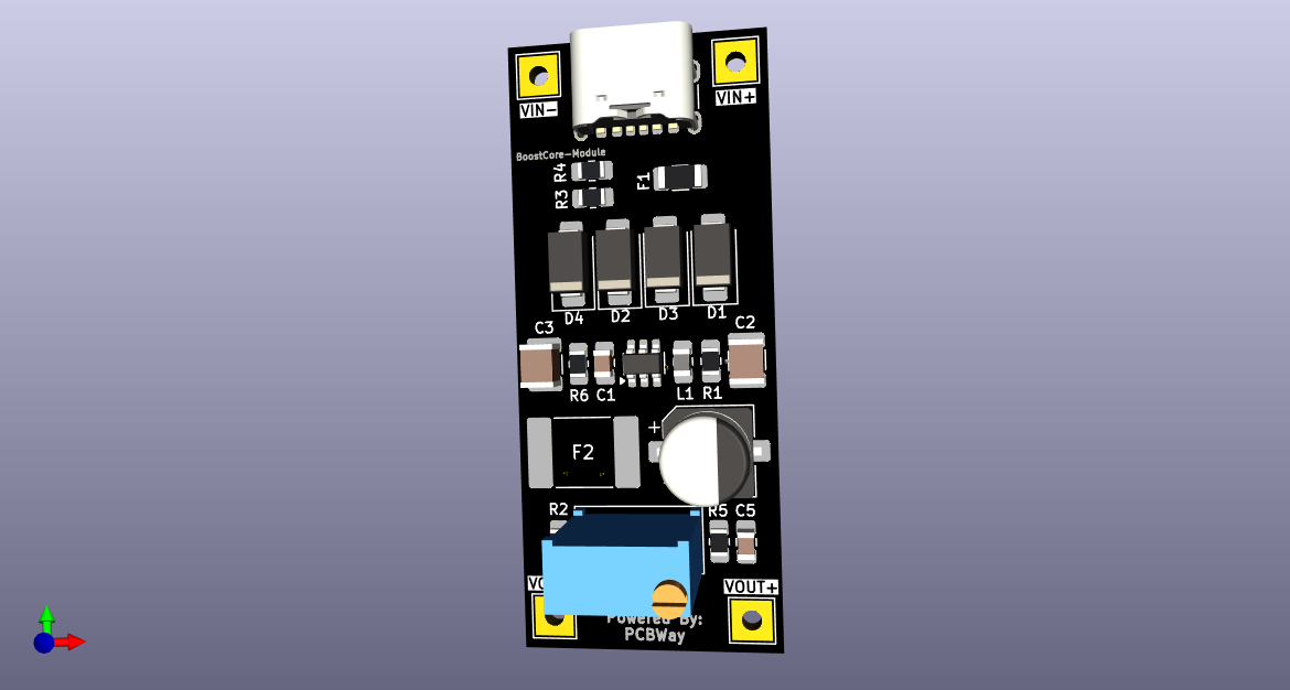
BoostCore Module is an open-source printed circuit board by hamzadenizyilmaz, from the hamzadenizyilmaz/BoostCore-Module repository on GitHub, published under the AGPL-3.0 licence. It is a 2-layer board of 19.7 × 46.3 mm with 27 parts on 15 nets, routed with 115 tracks and 11 vias.
It is built around the MT3608, SS36 and FSMD185-2920-R, with the P4SMAJ5.0_R1_00001 among its other parts. Its parts include 6 resistors, 5 capacitors, 5 diodes, 2 fuses and 1 IC. It belongs with the power boards of this library.


BoostCore-Module is a compact adjustable DC-DC step-up boost converter module built around the MT3608 regulator.
It supports USB-C 5V input, an optional external VIN input, Schottky OR-ing input selection, resettable fuse protection, TVS protection on USB VBUS, and a trimpot-adjustable output feedback network.
PCB manufacturing sponsor: This project is sponsored by PCBWay.
PCBWay support is mentioned in the documentation because the PCB is intended to be published as an open hardware project and manufactured as a compact prototype board.
This project is sponsored by PCBWay.
PCBWay is mentioned here as the PCB manufacturing sponsor for the open hardware release of BoostCore-Module. The board was designed with prototype manufacturing in mind, including compact routing, silkscreen labels, test points, and an export-ready project structure.
| Parameter | Value |
|---|---|
| Controller IC | MT3608 |
| Topology | Boost / step-up |
| USB-C input | 5V only |
| External VIN input | 2V-24V target range |
| Output voltage | Adjustable by RV1 trimpot |
| Switching frequency | MT3608 typical 1.2MHz |
| Inductor | 4.7uH recommended |
| Main boost diode | SS36, 3A, 60V |
| Output adjustment | R1 + R2 + RV1 feedback network |
| Output capacitor caution | Use 50V capacitors for high output voltage |
The adjustable output stage is:
VOUT -> R2 10k -> RV1 100k trimpot -> FB -> R1 2.2k -> GNDRecommended trimpot wiring:
RV1 pin 3 -> R2 side
RV1 pin 1 + pin 2 -> FB node
Formula:
VOUT = 0.6 x (1 + R_UPPER / R1)Where:
R_UPPER = R2 + active RV1 resistance
R1 = 2.2k
Important:
The USB-C connector is used as a 5V power-only input.
Required CC resistors:
CC1 -> 5.1k -> GND
CC2 -> 5.1k -> GND
USB-PD negotiation is not implemented. The USB-C input is therefore 5V only.
Current selected part:
F1 = KLM3S300RY
PTC resettable fuse
1206 / 3A / 6V
USB-C 5V input only
Do not use this part on the 24V external input path.
Compact option:
F2 = MF-MSMF110/24X-2
1812 / 1.1A / 24V
Higher-current but larger option:
F2_ALT = FSMD185-2920-R
2920 / 1.85A / 33V
D2 must be a 5V TVS diode, not a Schottky diode.
Recommended:
D2 = P4SMAJ5.0_R1_00001The board uses SS36 diodes:
D1 = SS36
D3 = SS36
D4 = SS36
D3 and D4 are used for input OR-ing.
If using the compact electrolytic output capacitor:
C4 (+) -> VOUT
C4 (-) -> GND
Mark polarity clearly on silkscreen.
Boost converters are layout-sensitive. Follow these rules:
U1 pin 1 SW + L1 right side + D1 anodeRecommended assembly sequence:
Before applying power:
Initial test:
1. Apply input power.
2. Measure VIN_SYS.
3. Measure VOUT.
4. Adjust RV1 slowly.
5. Verify output under light load.
6. Check temperature of MT3608, L1 and D1.Released as open hardware documentation. See LICENSE.
This is an open hardware project. Use at your own risk. Verify all footprints, ratings, clearances, capacitor voltage ratings and component stock before fabrication or ordering.
| Qty | Value | Footprint | References |
|---|---|---|---|
| 3 | SS36 | Diode_SMD:D_SMA | D1, D3, D4 |
| 2 | 22µF/50V/X7R | Capacitor_SMD:C_1210_3225Metric | C2, C3 |
| 2 | 5.1k | Resistor_SMD:R_0805_2012Metric_Pad1.20x1.40mm_HandSolder | R3, R4 |
| 2 | VIN_IN | TestPoint:TestPoint_THTPad_3.0x3.0mm_Drill1.5mm | VIN-, VIN+ |
| 1 | (GND) | TestPoint:TestPoint_THTPad_3.0x3.0mm_Drill1.5mm | VOUT- |
| 1 | (VOUT) | TestPoint:TestPoint_THTPad_3.0x3.0mm_Drill1.5mm | TP_VOUT2 |
| 1 | 100k | Resistor_SMD:R_0805_2012Metric_Pad1.20x1.40mm_HandSolder | R6 |
| 1 | 100k | Potentiometer_THT:Potentiometer_Bourns_3296W_Vertical | RV1 |
| 1 | 100nF/50V/X7R | Capacitor_SMD:C_0805_2012Metric_Pad1.18x1.45mm_HandSolder | C1 |
| 1 | 10K | Resistor_SMD:R_0805_2012Metric_Pad1.20x1.40mm_HandSolder | R5 |
| 1 | 10k | Resistor_SMD:R_0805_2012Metric_Pad1.20x1.40mm_HandSolder | R2 |
| 1 | 2.2k | Resistor_SMD:R_0805_2012Metric_Pad1.20x1.40mm_HandSolder | R1 |
| 1 | 4.7 µH | Inductor_SMD:L_0805_2012Metric_Pad1.15x1.40mm_HandSolder | L1 |
| 1 | 47pF/50V/X7R | Capacitor_SMD:C_0805_2012Metric_Pad1.18x1.45mm_HandSolder | C5 |
| 1 | FSMD185-2920-R | Fuse:Fuse_2920_7451Metric | F2 |
| 1 | KLM3S300RY FUSE | Fuse:Fuse_1206_3216Metric | F1 |
| 1 | MRS-050V100ME054-T/R | Capacitor_SMD:CP_Elec_6.3x5.4 | C4 |
| 1 | MT3608 | Package_TO_SOT_SMD:SOT-23-6 | U2 |
| 1 | P4SMAJ5.0_R1_00001 | Diode_SMD:D_SMA | D2 |
| 1 | PWR_LED | LED_SMD:LED_0805_2012Metric | D5 |
| 1 | USB_C_Receptacle_PowerOnly_6P | Connector_USB:USB_C_Receptacle_GCT_USB4125-xx-x-0190_6P_TopMnt_Horizontal | J1 |
The 26 most common of 27 parts.

FaisalHussain95/esp32-espnow-led-spots
DIY 220VAC LED spot controller — ESP32-C3 + COB LED + PT4115 PWM dimming, NTC thermal protection, active fan cooling, ESP-NOW mesh. WiFi bridge for Home Assistant (MQTT).


aeonSolutions/AeonLabs-AI-Volvo-MKII-Open-Hardware
Volvo MKII Open Hardware

exico91/SommerESP
A plug and play ESP32-C3 board to control Sommer garage doors


It measures 19.7 × 46.3 mm and has 2 copper layers, 1.6 mm thick.
27 parts, built around the MT3608, SS36, FSMD185-2920-R and P4SMAJ5.0_R1_00001. The full list of its parts is on this page, with links to each part's symbol and footprint where PCBKit's library has them.
From the hamzadenizyilmaz/BoostCore-Module repository on GitHub, at the commit this page was made from: the board is hardware/kicad/BoostCore Module.kicad_pcb and its schematic hardware/kicad/BoostCore Module.kicad_sch. PCBKit opens the board in the browser, with nothing to install.
Its repository publishes it under the AGPL-3.0 licence: you may reuse it on that licence's terms (keep the author's notice, and for a copyleft licence share your changes alike).