4 layers59 × 34.5 mm
 hackwerken/SensorGrid-PCB
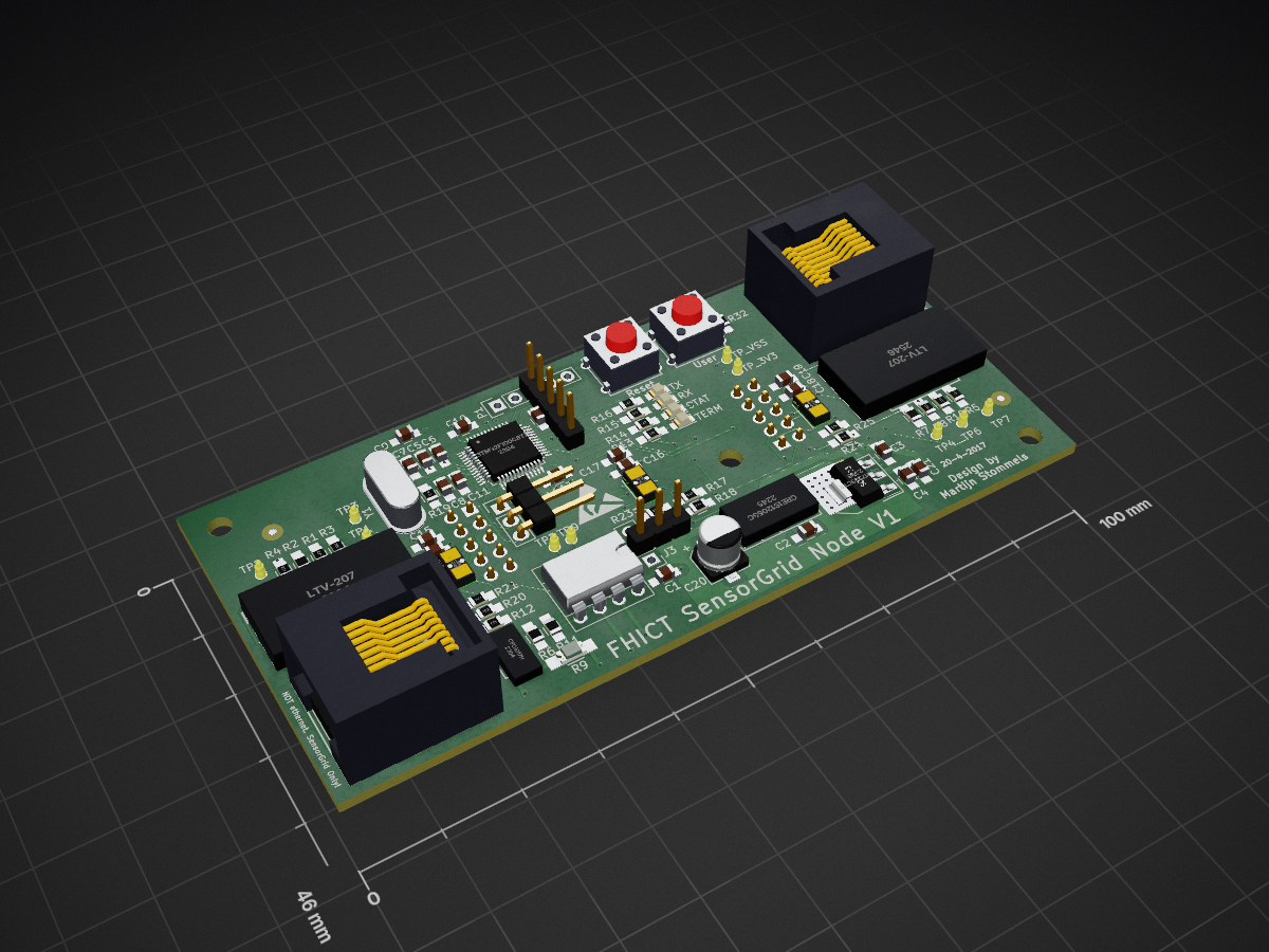
SensorGrid PCB is an open-source printed circuit board by hackwerken, from the hackwerken/SensorGrid-PCB repository on GitHub. It is a 4-layer board of 100 × 46 mm with 89 parts on 70 nets, routed with 880 tracks and 142 vias.
It is built around the MAX3075EM/TR, LTV-207 and CPC1017N, with the CRE1S1205SC and LD1117S33CTR-HXY among its other parts. Its parts include 26 resistors, 21 capacitors, 10 ICs, 9 connectors and 4 diodes. It belongs with the STM32 boards of this library.


| Qty | Value | Footprint | References |
|---|---|---|---|
| 12 | 100n | Capacitors_SMD:C_0805_HandSoldering | C1, C2, C3, C6, C10, C11, C12, C13, C14, C16, C18, C21 |
| 6 | 10k | Resistors_SMD:R_0805_HandSoldering | R20, R21, R22, R23, R24, R25 |
| 6 | 470 | Resistors_SMD:R_0805_HandSoldering | R1, R5, R13, R14, R15, R16 |
| 4 | 220 | Resistors_SMD:R_0805_HandSoldering | R4, R10, R19, R32 |
| 4 | NM | Resistors_SMD:R_0805_HandSoldering | R2, R6, R7, R11 |
| 3 | 1k | Resistors_SMD:R_0805_HandSoldering | R3, R8, R12 |
| 3 | 4.7u | Capacitors_SMD:C_0805_HandSoldering | C15, C17, C19 |
| 2 | 18p | Capacitors_SMD:C_0805_HandSoldering | C7, C8 |
| 2 | 1u | Capacitors_SMD:C_0805_HandSoldering | C5, C9 |
| 2 | 4.7k | Resistors_SMD:R_0805_HandSoldering | R17, R18 |
| 2 | LTV-207 | modlib:SOP8 | U1, U2 |
| 1 | 10u | Capacitors_SMD:C_0805_HandSoldering | C4 |
| 1 | 120 | Resistors_SMD:R_1206_HandSoldering | R9 |
| 1 | CONN_A | Socket_Strips:Socket_Strip_Straight_1x05_Pitch2.54mm | J4 |
| 1 | CONN_B | Socket_Strips:Socket_Strip_Straight_1x05_Pitch2.54mm | J5 |
| 1 | CONN_DEBUG | Pin_Headers:Pin_Header_Straight_1x03 | P2 |
| 1 | CONN_SAT_A | Pin_Headers:Pin_Header_Straight_2x05_Pitch2.54mm | J6 |
| 1 | CONN_SAT_B | Pin_Headers:Pin_Header_Straight_2x05_Pitch2.54mm | J7 |
| 1 | CONN_SWD | Pin_Headers:Pin_Header_Straight_1x05 | P1 |
| 1 | CONN_UART1 | Pin_Headers:Pin_Header_Straight_1x03_Pitch2.54mm | J3 |
| 1 | CPC1017N | modlib:CPC1017N | U4 |
| 1 | CRE1S1205SC | CRE1S:CRE1S | U5 |
| 1 | CRYSTAL_8MHz | Crystals:Crystal_HC49-U_Vertical | Y1 |
| 1 | LD1117S33CTR | TO_SOT_Packages_SMD:SOT-223 | U6 |
| 1 | MAX3075E | Housings_DIP:DIP-8_W7.62mm_Socket | U3 |
| 1 | NM | Capacitors_SMD:CP_Elec_5x5.7 | C20 |
| 1 | RJ45_A | Connect:RJ45_8 | J1 |
| 1 | RJ45_B | Connect:RJ45_8 | J2 |
| 1 | RX | LEDs:LED_0805 | D3 |
| 1 | STAT | LEDs:LED_0805 | D2 |
| 1 | STM32F100C8Tx | Housings_QFP:LQFP-48_7x7mm_Pitch0.5mm | U7 |
| 1 | SW_RESET | Buttons_Switches_ThroughHole:SW_PUSH_SMALL | SW1 |
| 1 | SW_USER | Buttons_Switches_ThroughHole:SW_PUSH_SMALL | SW2 |
| 1 | TERM | LEDs:LED_0805 | D1 |
| 1 | TP_3.3v | Measurement_Points:Measurement_Point_Round-SMD-Pad_Small | TP_3V3 |
| 1 | TP_ADDRESS_A | Measurement_Points:Measurement_Point_Round-SMD-Pad_Small | TP3 |
| 1 | TP_ADDRESS_B | Measurement_Points:Measurement_Point_Round-SMD-Pad_Small | TP7 |
| 1 | TP_ADDRESS_IN_A | Measurement_Points:Measurement_Point_Round-SMD-Pad_Small | TP1 |
| 1 | TP_ADDRESS_IN_B | Measurement_Points:Measurement_Point_Round-SMD-Pad_Small | TP4 |
| 1 | TP_ADDRESS_OUT_A | Measurement_Points:Measurement_Point_Round-SMD-Pad_Small | TP2 |
| 1 | TP_ADDRESS_OUT_B | Measurement_Points:Measurement_Point_Round-SMD-Pad_Small | TP6 |
| 1 | TP_UART1_DE | Measurement_Points:Measurement_Point_Round-SMD-Pad_Small | TP5 |
| 1 | TP_UART1_RE | Measurement_Points:Measurement_Point_Round-SMD-Pad_Small | TP9 |
| 1 | TP_VSS | Measurement_Points:Measurement_Point_Round-SMD-Pad_Small | TP_VSS |
| 1 | TX | LEDs:LED_0805 | D4 |
| 1 | VL53L0X_A | VL53L0X:VL53L0X | U8 |
| 1 | VL53L0X_B | VL53L0X:VL53L0X | U9 |
| 1 | VL53L0X_C | VL53L0X:VL53L0X | U10 |
The 83 most common of 89 parts.
It measures 100 × 46 mm and has 4 copper layers, 1.6 mm thick.
89 parts, built around the MAX3075EM/TR, LTV-207, CPC1017N and CRE1S1205SC. The full list of its parts is on this page, with links to each part's symbol and footprint where PCBKit's library has them.
From the hackwerken/SensorGrid-PCB repository on GitHub, at the commit this page was made from: the board is sensorGridPcb.kicad_pcb. PCBKit opens the board in the browser, with nothing to install.
Its repository states no licence, so its author keeps all rights: ask hackwerken before reusing the design.

nsm81/VehicleJunctionBox_PCBs
The junction box is an intermediate stage between the accumulator and inverter. It contains an HVD, a current sensor, discharge circuitry, TSAL and TSMPs.

dnatov/AutoWire-Cutter-Stripper
This repository is for documenting the process and project of creating our own automatic wire cutter. The device will be able to take input from the user regarding wire length, options and number of wires.

KLFAMO/phase_detector_Artiq
This is a phase detector designed to measure phase differences for input frequencies ranging from 0 to approximately 200 MHz. The device includes configurable frequency dividers for each input channel.

LJBlaauw/project_upgrade_3018pro_CNC
Het project is gebaseerd op opensource tools: - Freecad (3D parametrichs CAD) - Prusa slicer (3D printables voor Z unit en moerhouders - Kicad (PCB CAD ontwerp pico CNC, firmware GRBL webbuilder) - librecad (2D CAD) -…

meznak/helmet-signal-pcb
Printed circuit boards for my wireless helmet signal ( https://github.com/meznak/helmet-signal )

limpkin/xt60_parallelizer
a custom board to monitor custom battery packs
