
2 layers68.5 × 53.5 mm

A WiFi shield for the Arduino-hackAir library
Shield is an open-source printed circuit board by hackair-project, from the hackair-project/hackAir-ArduinoWiFi repository on GitHub. It is a 2-layer board of 68.6 × 53.3 mm with 27 parts on 51 nets, routed with 189 tracks and 7 vias.
It is built around the LD1117S33CTR-HXY, SN74LVC245AN and ZVN4206A. Its parts include 7 capacitors, 6 connectors, 4 ICs, 2 resistors and 1 transistor. It belongs with the radio and wireless boards and the ESP8266 boards of this library.



hackAIR is an EU-funded project aiming to develop an open technology platform for citizen observatories on air quality. Air pollution is an environmental issue with serious health and lifespan implications. However, it remains difficult for citizens to assess their exposure to air pollution and air quality issues in their country. Official air quality sensors are often few and far between, coverage is poor outside cities, and their data is not always easily accessible.
The hackAIR WiFi shield is a do-it-yourself solution for adding wireless connectivity to an Arduino node on the cheap. It's based around a custom PCB and the ESP8266 WiFi module and it's supported by the hackAIR firmware. All the network-related work is done by the WiFi module that can be controlled by simple serial commands. The hackAIR library for Arduino contains helpful wrapper functions to make using the shield easy and simple.
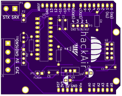
PCBs can be ordered directly from OSHPark here. The source files are included in this repository so anyone can order from their manufacturer of choice. Work is being done to make complete kits available soon.
Documentation for this shield is under construction here.
The PCB is designed using the open source EDA called KiCad. The PCB render shown above is created using PcbDraw.
Initial release
| Qty | Value | Footprint | References |
|---|---|---|---|
| 4 | Pin_Headers:Pin_Header_Straight_1x01 | HOLE, HOLE, HOLE, HOLE | |
| 2 | 100nF | Capacitors_ThroughHole:C_Disc_D3_P2.5 | C4, C7 |
| 2 | 10nF | Capacitors_ThroughHole:C_Disc_D3_P2.5 | C3, C6 |
| 2 | 10uF | Capacitors_ThroughHole:C_Radial_D5_L11_P2.5 | C2, C5 |
| 1 | 150 | Resistors_ThroughHole:Resistor_Horizontal_RM10mm | R1 |
| 1 | 1K | Resistors_ThroughHole:Resistor_Horizontal_RM10mm | R2 |
| 1 | 220uF | Capacitors_ThroughHole:C_Radial_D6.3_L11.2_P2.5 | C1 |
| 1 | ARDUINO_SHIELD | arduino_shields:ARDUINO_SHIELD_2_040pins | SHIELD1 |
| 1 | CONN_PWR | Connect:bornier3 | P1 |
| 1 | CONN_PWR_H | Pin_Headers:Pin_Header_Straight_1x03 | P4 |
| 1 | CONN_SENSOR | Connect:bornier5 | P3 |
| 1 | CONN_SENSOR_H | Pin_Headers:Pin_Header_Straight_1x05 | P6 |
| 1 | CONN_SENSOR_SERIAL | Connect:bornier2 | P2 |
| 1 | CONN_SENSOR_SERIAL_H | Pin_Headers:Pin_Header_Straight_1x02 | P5 |
| 1 | ESP-01v090 | ESP8266:ESP-01 | U3 |
| 1 | ESP-12 | ESP8266:ESP-12 | U4 |
| 1 | Jumper_NO_Small | Pin_Headers:Pin_Header_Straight_1x02 | JP1 |
| 1 | LD1117S33CTR | TO_SOT_Packages_THT:TO-220_Neutral123_Vertical_MountedFromLS_LargePads | U1 |
| 1 | LOGO | lib:logo | G*** |
| 1 | SN74LVC245A | Housings_DIP:DIP-20_W7.62mm_LongPads | U2 |
| 1 | ZVN4206A | TO_SOT_Packages_THT:TO-92_Inline_Wide | Q1 |
It measures 68.6 × 53.3 mm and has 2 copper layers, 1.6 mm thick.
27 parts, built around the LD1117S33CTR-HXY, SN74LVC245AN and ZVN4206A. The full list of its parts is on this page, with links to each part's symbol and footprint where PCBKit's library has them.
From the hackair-project/hackAir-ArduinoWiFi repository on GitHub, at the commit this page was made from: the board is Schematic & PCB/Version 1/shield.kicad_pcb. PCBKit opens the board in the browser, with nothing to install.
Its repository states no licence, so its author keeps all rights: ask hackair-project before reusing the design.


jabadiagm/MSXhdmi_tn20k
Adaptador hdmi para MSX con Tang Nano 20k


wangyeee/OpenHardware
Collections of hardware design related to my drone project.