

2 layers75.5 × 71 mm

 hachiojipm/aimai7
aimai is an "FM transceiver" name tag based on ESP32
Aimai is an open-source printed circuit board by hachiojipm, from the hachiojipm/aimai repository on GitHub. It is a 2-layer board of 158.8 × 101.6 mm with 37 parts on 54 nets, routed with 453 tracks and 32 vias.
It is built around the ESP32-DEVKITC-VE and WS2812B. Its parts include 11 capacitors, 4 connectors, 4 switches, 3 ICs and 3 diodes. It belongs with the radio and wireless boards and the ESP32 boards of this library.
(Japanese doc is here: README_ja)

aimai is an "FM transceiver" name tag based on ESP32.
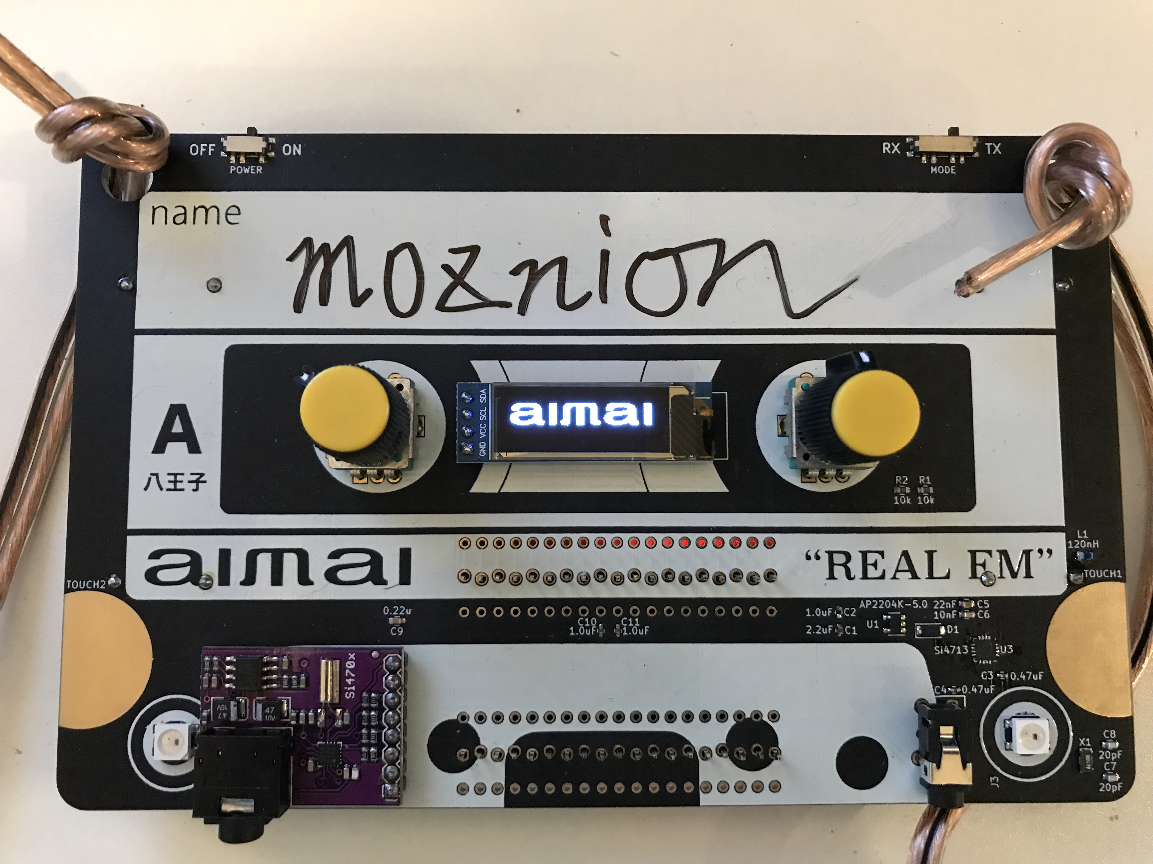
HIGHLY RECOMMENDED: it should be plugged earphones into the RX module's (purple one) phone jack because the earphones line works as an antenna. If not, it might be not able to receive text data through RDS.
$ make bootstrap$ make build$ make uploadIf you have something trouble, please edit the upload_port configuration on platformio.ini.
A schematic and PCB data are here: pcb
This project is optimized for Japan coverage. If you would like to use this device in countries other than Japan, you should modify the code of frequency band for Si4703 and Si4713.
| Qty | Value | Footprint | References |
|---|---|---|---|
| 4 | Battery_Cell | awia:AAA-holder | BT1, BT2, BT3, BT4 |
| 3 | 1.0uF | Capacitors_SMD:C_0402 | C2, C10, C11 |
| 2 | 0.47uF | Capacitors_SMD:C_0402 | C3, C4 |
| 2 | 10k | Capacitors_SMD:C_0603 | R1, R2 |
| 2 | 20pF | Capacitors_SMD:C_0603 | C7, C8 |
| 2 | Rotary_Encoder_Switch | Rotary_Encoder:RotaryEncoder_Alps_EC12E-Switch_Vertical_H20mm | SW2, SW3 |
| 2 | WS2812B | LED_SMD:LED_WS2812B_PLCC4_5.0x5.0mm_P3.2mm | D2, D3 |
| 2 | touchpad | awia:touchpad | TOUCH1, TOUCH2 |
| 1 | 0.22u | Capacitors_SMD:C_0603 | C9 |
| 1 | 10nF | Capacitors_SMD:C_0603 | C6 |
| 1 | 120nH | Inductors_NEOSID:Neosid_Inductor_SM0603CG | L1 |
| 1 | 1N4148 | Diodes_SMD:D_SOD-123 | D1 |
| 1 | 2.2uF | Capacitors_SMD:C_0402 | C1 |
| 1 | 22nF | Capacitors_SMD:C_0603 | C5 |
| 1 | 32.768K | Crystals:Crystal_SMD_3215-2pin_3.2x1.5mm | X1 |
| 1 | ANT | Pin_Headers:Pin_Header_Straight_1x01_Pitch2.54mm | J4 |
| 1 | AP2204K-5.0 | TO_SOT_Packages_SMD:SOT-23-5 | U1 |
| 1 | AudioJack3 | awia:ST-005-G | J3 |
| 1 | ESP32-DevKitC | awia:ESP32-DevKitC | U2 |
| 1 | LOGO | awia:awia_silk | G1 |
| 1 | LOGO | awia:awia_silk_back | G2 |
| 1 | MODE | Buttons_Switches_SMD:SW_SP3T_PCM13 | SW4 |
| 1 | OLED | awia:SSD1306-128x32-Module | J1 |
| 1 | POWER | Buttons_Switches_SMD:SW_SPDT_PCM12 | SW1 |
| 1 | RX_Board | awia:Si4703-Module | J2 |
| 1 | Si4713 | Housings_DFN_QFN:SiliconLabs_QFN-20-1EP_3x3mm_Pitch0.5mm | U3 |


EsqueletoArg/HexaProyecto
Un ajedrez de 3x3 casillas, donde se enfrentan 3 peones de ambos bandos para inmovilizar al rival o llegar al otro lado del tablero.


melektron/htl_day_demo_projects
This board connects an HC-SR04 ultrasonic sensor, OLED display and WS2812B LED-Strip to an ESP32 DevKitC. It also includes a barrel jack for power.


Rikeroo/habit-reminder
Low energy physical habit reminder, using RGB LEDs, a small task screen and tactile switches to build useful habits and get tasks done
It measures 158.8 × 101.6 mm and has 2 copper layers, 1.6 mm thick.
37 parts, built around the ESP32-DEVKITC-VE and WS2812B. The full list of its parts is on this page, with links to each part's symbol and footprint where PCBKit's library has them.
From the hachiojipm/aimai repository on GitHub, at the commit this page was made from: the board is pcb/aimai.kicad_pcb. PCBKit opens the board in the browser, with nothing to install.
Its repository states no licence, so its author keeps all rights: ask hachiojipm before reusing the design.