2 layers78.8 × 79.8 mm
Heart-555-Timer
aayanrahman/Heart-555-Timer
A heart 555 timer I made for ... myself? Might make a document on how to make it
30 parts

 h-buter/Flipklok
Welcome to the repository for my project as part of my Bachelor's degree in Electronics at Windesheim. This project involves creating a flip clock inspired by the design from the 1970s, which is synchronized using time…
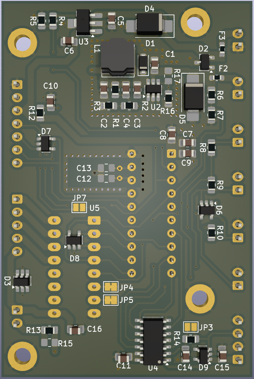
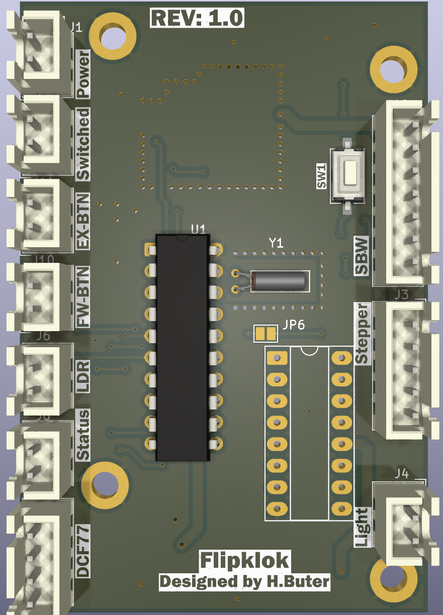
Flipklok is an open-source printed circuit board by h-buter, from the h-buter/Flipklok repository on GitHub. It is a 2-layer board of 48 × 72 mm with 70 parts on 51 nets, routed with 418 tracks and 135 vias.
It is built around the MSP430G2553IN20, 74HC00D and AP2205-W5, with the ULQ2003A, ESDA5V3SC5 and ESDA19SC6 among its other parts. Its parts include 16 capacitors, 16 resistors, 10 connectors, 9 diodes and 5 ICs. It belongs with the MSP430 boards of this library.


 |  |
|---|---|
Welcome to the repository for my project as part of my Bachelor's degree in Electronics at Windesheim. This project involves creating a flip clock inspired by the design from the 1970s, which is synchronized using time information from the DCF77 long-wave time signal. The goal is to ensure that this electronic and electromechanical device operates efficiently within a low power environment.
At time of writing I am still deciding on if the clock will be used a desk clock or if I build it in to my 1977 Relaint Robin MK1 This is why some design decisions, like low power, are not always directly clear in the scope of a normal clock project.
For the complete documentation see the doxygen documentation hosted on GitHub pages:
This flip clock project integrates both mechanical components and electronics to display the current time accurately based on data received from the DCF77 transmitter located in Germany. Designed with energy efficiency in mind, the clock maintains continuous time tracking to compensate for any potential reception limitations of the DCF77 signal while minimizing power consumption.
Mechanical and Time Management: The project requires careful application of mechanics and efficient time management techniques to ensure the device functions optimally on a 12V source.
Integration of Electronics and Electromechanics: Incorporating electronic components like motors and sensors for position detection into the mechanical design poses significant challenges.
PCB Design: The creation of a custom PCB is necessary to accommodate all electronic components while maintaining compactness and efficiency.
DCF77 Protocol Implementation: Applying the DCF77 protocol ensures accurate time synchronization. This involves handling signals and data correctly within the system’s constraints.
Software Development: The software component, developed in C with some sections written in assembly language, is responsible for processing DCF77 data and controlling stepper or servo motors to operate the flip clock.
The software aspect focuses on:
The hardware component involves:
To get started with this project, you need to:
Contributions are welcome! Whether it's optimizing the code for better performance or suggesting improvements in hardware integration, your input is valuable.
This project is licensed under to be determined
Thank you for exploring this unique blend of vintage design and electronics. Should you have any questions or suggestions regarding this project, feel free to open an issue or contact me directly.
| Qty | Value | Footprint | References |
|---|---|---|---|
| 5 | 10k | Resistor_SMD:R_0805_2012Metric_Pad1.20x1.40mm_HandSolder | R8, R9, R10, R14, R16 |
| 4 | 0.1uF | Capacitor_SMD:C_0805_2012Metric_Pad1.18x1.45mm_HandSolder | C9, C11, C15, C16 |
| 4 | ESDA5V3SC5 | Package_TO_SOT_SMD:SOT-23-5 | D6, D7, D8, D9 |
| 4 | MountingHole_Pad | MountingHole:MountingHole_3.2mm_M3_DIN965_Pad_TopBottom | H1, H2, H3, H4 |
| 2 | 18k | Resistor_SMD:R_0805_2012Metric_Pad1.20x1.40mm_HandSolder | R5, R7 |
| 2 | 75k | Resistor_SMD:R_0805_2012Metric_Pad1.20x1.40mm_HandSolder | R4, R6 |
| 2 | Bridged | Jumper:SolderJumper-2_P1.3mm_Bridged_Pad1.0x1.5mm | JP4, JP5 |
| 2 | C_x | Capacitor_SMD:C_0805_2012Metric_Pad1.18x1.45mm_HandSolder | C12, C13 |
| 2 | Fuse | Fuse:Fuse_0603_1608Metric_Pad1.05x0.95mm_HandSolder | F2, F3 |
| 2 | S2A 50V 1.5A | Diode_SMD:D_SMB_Handsoldering | D4, D5 |
| 1 | 0,22uF | Capacitor_SMD:C_0805_2012Metric_Pad1.18x1.45mm_HandSolder | C3 |
| 1 | 100k | Resistor_SMD:R_0805_2012Metric_Pad1.20x1.40mm_HandSolder | R17 |
| 1 | 100n | Capacitor_SMD:C_0805_2012Metric_Pad1.18x1.45mm_HandSolder | C14 |
| 1 | 100pF | Capacitor_SMD:C_0805_2012Metric_Pad1.18x1.45mm_HandSolder | C4 |
| 1 | 10uF | Capacitor_SMD:C_0805_2012Metric_Pad1.18x1.45mm_HandSolder | C7 |
| 1 | 10uF 16V X5R | Capacitor_SMD:C_0805_2012Metric_Pad1.18x1.45mm_HandSolder | C2 |
| 1 | 15k | Resistor_SMD:R_0805_2012Metric_Pad1.20x1.40mm_HandSolder | R2 |
| 1 | 1nF | Capacitor_SMD:C_0805_2012Metric_Pad1.18x1.45mm_HandSolder | C10 |
| 1 | 1uF | Capacitor_SMD:C_0805_2012Metric_Pad1.18x1.45mm_HandSolder | C8 |
| 1 | 1uF 25V X7R | Capacitor_SMD:C_0805_2012Metric_Pad1.18x1.45mm_HandSolder | C5 |
| 1 | 2.2uF 10V X7R | Capacitor_SMD:C_0805_2012Metric_Pad1.18x1.45mm_HandSolder | C6 |
| 1 | 28BYJ-48 | Connector_JST:JST_XH_B5B-XH-A_1x05_P2.50mm_Vertical | J3 |
| 1 | 4.7uF 25V X5R | Capacitor_SMD:C_0805_2012Metric_Pad1.18x1.45mm_HandSolder | C1 |
| 1 | 470 | Resistor_SMD:R_0805_2012Metric_Pad1.20x1.40mm_HandSolder | R13 |
| 1 | 47k | Resistor_SMD:R_0805_2012Metric_Pad1.20x1.40mm_HandSolder | R12 |
| 1 | 500 | Resistor_SMD:R_0805_2012Metric_Pad1.20x1.40mm_HandSolder | R3 |
| 1 | 74HC00 | Package_SO:SOIC-14_3.9x8.7mm_P1.27mm | U4 |
| 1 | 82k | Resistor_SMD:R_0805_2012Metric_Pad1.20x1.40mm_HandSolder | R1 |
| 1 | AP2205 | Package_TO_SOT_SMD:SOT-89-3_Handsoldering | U3 |
| 1 | Backlight | Connector_JST:JST_XH_B2B-XH-A_1x02_P2.50mm_Vertical | J4 |
| 1 | Bypass-LDF | Jumper:SolderJumper-2_P1.3mm_Open_Pad1.0x1.5mm | JP3 |
| 1 | DCF77 | Connector_JST:JST_XH_B4B-XH-A_1x04_P2.50mm_Vertical | J5 |
| 1 | ECS-.327-6-13X | Crystal:Crystal_C26-LF_D2.1mm_L6.5mm_Horizontal | Y1 |
| 1 | EN-RXD | Jumper:SolderJumper-2_P1.3mm_Open_Pad1.0x1.5mm | JP6 |
| 1 | EN-TXD | Jumper:SolderJumper-2_P1.3mm_Open_Pad1.0x1.5mm | JP7 |
| 1 | ESDA19SC6 | Package_TO_SOT_SMD:SOT-23-6_Handsoldering | D3 |
| 1 | ESDCAN01-2BLY | Package_TO_SOT_SMD:TSOT-23 | D2 |
| 1 | EX-btn | Connector_JST:JST_XH_B2B-XH-A_1x02_P2.50mm_Vertical | J11 |
| 1 | FW-btn | Connector_JST:JST_XH_B2B-XH-A_1x02_P2.50mm_Vertical | J10 |
| 1 | Indicator | Connector_JST:JST_XH_B2B-XH-A_1x02_P2.50mm_Vertical | J8 |
| 1 | LDR | Connector_JST:JST_XH_B2B-XH-A_1x02_P2.50mm_Vertical | J6 |
| 1 | MSP430G2553IN20 | Package_DIP:DIP-20_W7.62mm | U1 |
| 1 | PMEG3010ER 30V, 1A | Diode_SMD:D_SOD-123F | D1 |
| 1 | Power | Connector_JST:JST_XH_B2B-XH-A_1x02_P2.50mm_Vertical | J1 |
| 1 | Programheader | Connector_JST:JST_XH_B7B-XH-A_1x07_P2.50mm_Vertical | J12 |
| 1 | R | Resistor_SMD:R_0805_2012Metric_Pad1.20x1.40mm_HandSolder | R15 |
| 1 | Reset | Button_Switch_SMD:SW_Tactile_SPST_NO_Straight_CK_PTS636Sx25SMTRLFS | SW1 |
| 1 | SRN6045HA | Inductor_SMD:L_Bourns_SRN6045TA | L1 |
| 1 | SW | Connector_JST:JST_XH_B2B-XH-A_1x02_P2.50mm_Vertical | J2 |
| 1 | ULQ2003A | Package_DIP:DIP-16_W7.62mm_Socket_LongPads | U5 |
| 1 | ~ | Package_TO_SOT_SMD:SOT-23-6_Handsoldering | U2 |
aayanrahman/Heart-555-Timer
A heart 555 timer I made for ... myself? Might make a document on how to make it

entropia/jeopardy-helmets
An arduino hackery to create a visual buzzer for jeopardy


CU-Rocketry/flight_computer
Competition Flight Computer Module 25-26

atop8918/DigitalWaters_WD_prototype
Simplified Schematic for prototype release


It measures 48 × 72 mm and has 2 copper layers, 1.6 mm thick.
70 parts, built around the MSP430G2553IN20, 74HC00D, AP2205-W5 and ULQ2003A. The full list of its parts is on this page, with links to each part's symbol and footprint where PCBKit's library has them.
From the h-buter/Flipklok repository on GitHub, at the commit this page was made from: the board is PCB/Flipklok/Flipklok.kicad_pcb and its schematic PCB/Flipklok/Flipklok.kicad_sch. PCBKit opens the board in the browser, with nothing to install.
Its repository states no licence, so its author keeps all rights: ask h-buter before reusing the design.