2 layers120 × 110 mm

 gyuritill/DCC-Lokdecoder19
DCC locomotive decoder
Lokdecoder TI altQuartz is an open-source printed circuit board by gyuritill, from the gyuritill/DCC-Lokdecoder repository on GitHub, published under the CC0-1.0 licence. It is a 4-layer board of 22.9 × 15.8 mm with 63 parts on 51 nets, routed with 362 tracks and 30 vias.
It is built around the DRV8872DDAR and MIC5205-5.0YM5-TR. Its parts include 10 capacitors, 10 resistors, 8 diodes, 3 ICs and 1 crystal. It belongs with the AVR (ATmega, ATtiny) boards of this library.


DCC multifunction decoder for H0 locomotives
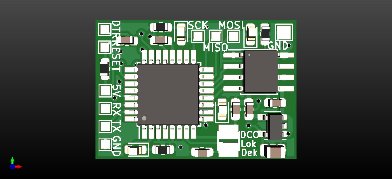 | 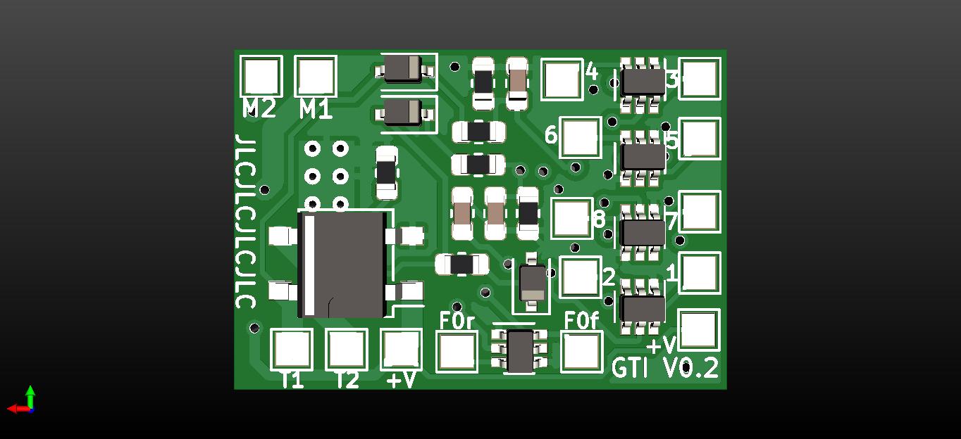 |
|---|---|
| top side | bottom side |
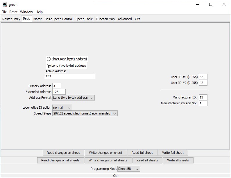 | 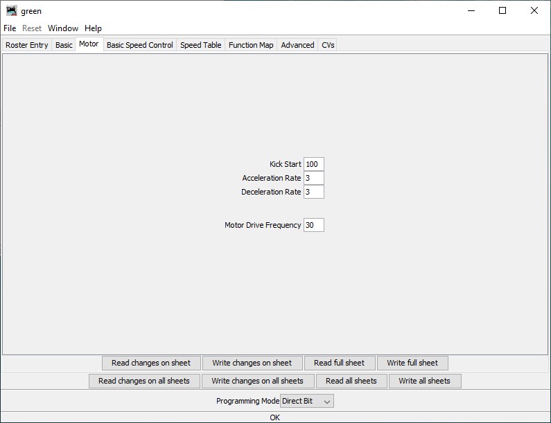 | 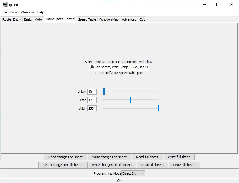 | 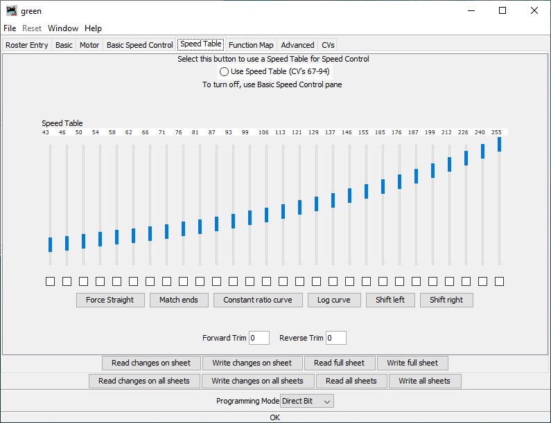 | 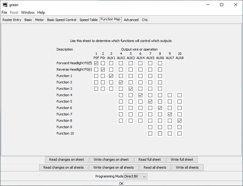 | 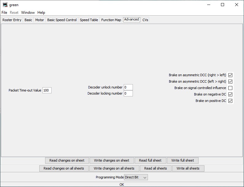 |
|---|---|---|---|---|---|
| Basic | Motor | Basic speed control | Speed table | Function map | Advanced |
#define RESET_FACTORY_DEFAULTS to fill the EEPROM with the default CV values#define RESET_FACTORY_DEFAULTS to avoid resetting to factory defaults every time.
| Pad | Function |
|---|---|
| M1 | Motor 1 |
| M2 | Motor 2 |
| T1 | Track 1 |
| T2 | Track 2 |
| V+ | Positive common for function outputs (keep-alive capacitor positive) |
| F0f | F0 function output forward (open drain) |
| F0r | F0 function output reverse (open drain) |
| 1-8 | AUX function output n (open drain) |
| 5V | internal microcontroller +5V supply |
| GND | ground (keep alive capacitor negative) |
| SCK | ISP programming clock (connect to ISP SCK) |
| MISO | ISP programming read (connect to ISP MISO) |
| MOSI | ISP programming write (connect to ISP MOSI) |
| RST | ISP programming reset (connect to ISP reset output) |
| RX | serial programming receive (connect to TTL UART TX) |
| TX | serial programming transmit (connect to TTL UART RX) |
| DTR | serial programming reset through a 100 nF capacitor (connect to TTL UART DTR) |
| Qty | Value | Footprint | References |
|---|---|---|---|
| 5 | 2N7002DWCT | Package_TO_SOT_SMD:SOT-363_SC-70-6 | T1, T2, T3, T4, T5 |
| 4 | 100nF | Capacitor_SMD:C_0603_1608Metric | C1, C2, C5, C10 |
| 4 | 1k | Resistor_SMD:R_0603_1608Metric | R7, R9, R10, R11 |
| 3 | 27k | Resistor_SMD:R_0603_1608Metric | R2, R3, R4 |
| 3 | 4.7k | Resistor_SMD:R_0603_1608Metric | R1, R5, R6 |
| 2 | +V | TestPoint:TestPoint_Pad_1.5x1.5mm | TP6, TP17 |
| 2 | 10pF | Capacitor_SMD:C_0603_1608Metric | C8, C9 |
| 2 | 4.7uF | Capacitor_SMD:C_0603_1608Metric | C6, C7 |
| 2 | NSR0530HT1G | Diode_SMD:D_SOD-323 | D3, D4 |
| 1 | 1 | TestPoint:TestPoint_Pad_1.5x1.5mm | TP9 |
| 1 | 16M | myCrystal:Crystal_SMD_2520-2Pin_2.5x2.0mm_HandSoldering | X1 |
| 1 | 2 | TestPoint:TestPoint_Pad_1.5x1.5mm | TP10 |
| 1 | 2.2uF | Capacitor_SMD:C_0805_2012Metric | C4 |
| 1 | 3 | TestPoint:TestPoint_Pad_1.5x1.5mm | TP11 |
| 1 | 4 | TestPoint:TestPoint_Pad_1.5x1.5mm | TP12 |
| 1 | 470pF | Capacitor_SMD:C_0603_1608Metric | C3 |
| 1 | 5 | TestPoint:TestPoint_Pad_1.5x1.5mm | TP13 |
| 1 | 5V | TestPoint:TestPoint_Pad_1.0x1.0mm | TP22 |
| 1 | 6 | TestPoint:TestPoint_Pad_1.5x1.5mm | TP14 |
| 1 | 7 | TestPoint:TestPoint_Pad_1.5x1.5mm | TP15 |
| 1 | 8 | TestPoint:TestPoint_Pad_1.5x1.5mm | TP16 |
| 1 | ATMEGA328P-AUR | Package_QFP:TQFP-32_7x7mm_P0.8mm | IC2 |
| 1 | Bl_LED | LED_SMD:LED_0603_1608Metric | D8 |
| 1 | DRV8872DDAR | Package_SO:Texas_HTSOP-8-1EP_3.9x4.9mm_P1.27mm_EP2.95x4.9mm_Mask2.4x3.1mm_ThermalVias | IC3 |
| 1 | DTR | TestPoint:TestPoint_Pad_1.0x1.0mm | TP25 |
| 1 | D_Bridge_+-AA | Package_TO_SOT_SMD:TO-269AA | D1 |
| 1 | F0f | TestPoint:TestPoint_Pad_1.5x1.5mm | TP7 |
| 1 | F0r | TestPoint:TestPoint_Pad_1.5x1.5mm | TP8 |
| 1 | GND | TestPoint:TestPoint_Pad_1.5x1.5mm | TP5 |
| 1 | GND | TestPoint:TestPoint_Pad_1.0x1.0mm | TP26 |
| 1 | Gr_LED | LED_SMD:LED_0603_1608Metric | D6 |
| 1 | M1 | TestPoint:TestPoint_Pad_1.5x1.5mm | TP1 |
| 1 | M2 | TestPoint:TestPoint_Pad_1.5x1.5mm | TP2 |
| 1 | MIC5205-5.0YM5-TR | Package_TO_SOT_SMD:SOT-23-5 | IC1 |
| 1 | MISO | TestPoint:TestPoint_Pad_1.0x1.0mm | TP20 |
| 1 | MM3Z4V7ST1G | Diode_SMD:D_SOD-323 | D2 |
| 1 | MOSI | TestPoint:TestPoint_Pad_1.0x1.0mm | TP21 |
| 1 | RESET | TestPoint:TestPoint_Pad_1.0x1.0mm | TP18 |
| 1 | RX | TestPoint:TestPoint_Pad_1.0x1.0mm | TP23 |
| 1 | Rd_LED | LED_SMD:LED_0603_1608Metric | D7 |
| 1 | SCK | TestPoint:TestPoint_Pad_1.0x1.0mm | TP19 |
| 1 | T1 | TestPoint:TestPoint_Pad_1.5x1.5mm | TP3 |
| 1 | T2 | TestPoint:TestPoint_Pad_1.5x1.5mm | TP4 |
| 1 | TX | TestPoint:TestPoint_Pad_1.0x1.0mm | TP24 |
| 1 | Ye_LED | LED_SMD:LED_0603_1608Metric | D5 |
It measures 22.9 × 15.8 mm and has 4 copper layers, 1.6 mm thick.
63 parts, built around the DRV8872DDAR and MIC5205-5.0YM5-TR. The full list of its parts is on this page, with links to each part's symbol and footprint where PCBKit's library has them.
From the gyuritill/DCC-Lokdecoder repository on GitHub, at the commit this page was made from: the board is KiCAD_project/Lokdecoder_TI_altQuartz/Lokdecoder_TI_altQuartz.kicad_pcb. PCBKit opens the board in the browser, with nothing to install.
Its repository publishes it under the CC0-1.0 licence: you may reuse it on that licence's terms (keep the author's notice, and for a copyleft licence share your changes alike).

loxodes/vna
Under development open hardware microwave vector network analyzer

pierre-muth/fast-flipdot
Driving a flipdot matrix differently. All dots simultaneously.

lab11/signpost
Exploring what happens when you put computers on sign posts.


AndersBNielsen/PhaseLatchMini
High-rate continuous streaming of interleaved dual ADC (I/Q) samples over USB Full‑Speed (FS) using only the built‑in CDC class on an STM32F103C8 ("Blue Pill" style) board.

jlcjak/neurband
Open, minimal sEMG wristband like the Meta Neural Band: 8-ch ADS1298 + nRF52832 BLE, dry gold electrodes on a flex, 3D-printed band. KiCad, FreeCAD, Zephyr, Python, simulations.
