

2 layers73.5 × 46.5 mm
SummingBoard
Gray-Stone/Simple-Audio-Mixer
Simple Audio Merger (SAM) is designed to be used for merging audio from 2 sources and simply output the added voltage to output.
15 parts
 Gray-Stone/Simple-Audio-Mixer
Simple Audio Merger (SAM) is designed to be used for merging audio from 2 sources and simply output the added voltage to output.
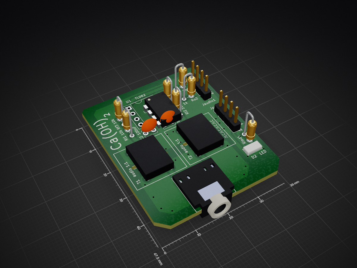
InputBuffer is an open-source printed circuit board by Gray-Stone, from the Gray-Stone/Simple-Audio-Mixer repository on GitHub. It is a 2-layer board of 39 × 47.5 mm with 16 parts on 15 nets, routed with 47 tracks and 32 vias.
It is built around the TL082 and SJ1-3525NG-PI. Its parts include 2 capacitors, 1 IC, 1 diode and 1 connector. It belongs with the audio and music boards of this library.
Design choices and reason for decision
Simple Audio Merger (SAM) is designed to be used for merging audio from 2 sources and simply output the added voltage to output. Input is design for common consumer appliances with stereo audio, and there will not be any processing other than summation on board. The output is only buffered (powered) by an Opamp, and a power amplifier should be used if the load is not high impedance (headphone, speaker is typical low impedance load).
3.5mm stereo audio jack will be used as audio interface for both input and output. This is the most common form of audio connection between desktop device and is simplest.
Possible choice of USB power and battery power.
Benefit of USB supply:
Problem with USB supply:
Huge amount of noise (USB data line, other USB devices, etc.)
Single Rail, and the lower rail is mains-earth reference (virtual ground cannot be connected with other devices)
Reason to choose battery supply:
Clean rail.
Easily generated negative rail (or virtual ground).
Since floating rail, no requirement before connecting ground with other device (virtual or not)
Problem with battery:
Need replace battery
Need a battery management system to detect low battery and shutoff/notice user before it causes problem
The USB high power rail noise is not much of a problem given all signal goes through Opamp, which have great rail rejection.
The battery replacement is not that bad, this design does not provide power amplifier. Most power are used by Opamp. So, replacement cycle is not as often. In addition, audio signal is basically below 1V, two AA battery will be enough for dual rails.
Both choices are ok, if a battery is chosen, then BMS is needed. If USB is chosen, negative rail is needed.
If USB power is used, a negative rail must be generated. Generate a half rail virtual ground is not suitable in this case.
A voltage reference is generally generated by a voltage buffer with input connect to a revers biased zener. The zener voltage is set by current, despite little, but still fluctuate with current change. The source current for zener voltage is usually set by resistor, which is voltage controlled current.
USB is mains-earth referenced ground. The audio ground from other device (input and output amplifier) is the same mains-earth reference as well. This means the virtual ground can not be connected to another device.
When using virtual ground, the output voltage is referenced to virtual ground. The voltage ripple across “negative rail” and virtual ground is considered rail noise. However, since other device is also ground referenced, they see they “negative rail” noise as a noise added to virtual ground. Since output is referenced to virtual ground, outside device also see this noise as part of the output signal (instead of common mode noise).
If battery is used, then a virtual ground is easily generated by connecting a lead from middle of the two batteries. This virtual ground will be push pull and very stable in voltage. Furthermore, battery is floating voltage device, the virtual ground can be connected to any mains-earth connection. This connection makes it remove some common-mode noise.
Audio signal are generally a voltage signal. One possible choice is to connect everything through a resistor to a summing point. The resistor turns the voltage signal into current signal. Then transconductance amplifier can easily turn that into output voltage.
In this case, the impedance each input device see depends on the resistance and other device it sees.
If each input is first buffered by an opamp, then all input device sees high impedance which is decoupled from others. In the case of a low impedance (high power) device on input side, buffer Opamp prevent other input device get loaded.
USB power source with negative rail (No BMS required, Opamp have good PSRR).
Opamp buffered input (Opamp are cheap, this is a one-off board).
| Qty | Value | Footprint | References |
|---|---|---|---|
| 4 | 10k | Resistors_THT:R_Axial_DIN0204_L3.6mm_D1.6mm_P2.54mm_Vertical | Rf3, Rf4, Ri1, Ri2 |
| 2 | 100nF | Capacitors_THT:C_Disc_D3.8mm_W2.6mm_P2.50mm | C1, C2 |
| 2 | 1k | Resistors_THT:R_Axial_DIN0204_L3.6mm_D1.6mm_P2.54mm_Vertical | Ro1, Ro2 |
| 2 | audio 1:1 | MISC:Audio Transformer | T1, T2 |
| 1 | 4k | Resistors_THT:R_Axial_DIN0204_L3.6mm_D1.6mm_P2.54mm_Vertical | Rled1 |
| 1 | LED | LEDs:LED_D2.0mm_W4.8mm_H2.5mm_FlatTop | D2 |
| 1 | SJ1_3525NG | MISC:Audio Barral SJ1-3525NG | J1 |
| 1 | TL082 | Housings_DIP:DIP-8_W7.62mm_Socket | U1 |
| 1 | audioConn1x4 | Socket_Strips:Socket_Strip_Straight_1x04_Pitch2.54mm | Jaudio1 |
| 1 | pwrConn1x4 | Socket_Strips:Socket_Strip_Straight_1x04_Pitch2.54mm | Jpwr1 |
It measures 39 × 47.5 mm and has 2 copper layers, 1.6 mm thick.
16 parts, built around the TL082 and SJ1-3525NG-PI. The full list of its parts is on this page, with links to each part's symbol and footprint where PCBKit's library has them.
From the Gray-Stone/Simple-Audio-Mixer repository on GitHub, at the commit this page was made from: the board is AudioMixer/InputBuffer/InputBuffer.kicad_pcb. PCBKit opens the board in the browser, with nothing to install.
Its repository states no licence, so its author keeps all rights: ask Gray-Stone before reusing the design.
Gray-Stone/Simple-Audio-Mixer
Simple Audio Merger (SAM) is designed to be used for merging audio from 2 sources and simply output the added voltage to output.

Gray-Stone/Simple-Audio-Mixer
Simple Audio Merger (SAM) is designed to be used for merging audio from 2 sources and simply output the added voltage to output.

fossasia/pslab-hardware
PSLab Hardware Design and Schematics https://pslab.io

QuantumVillage/UncutGem
A prototype Full Stack fully Open Source NV Center Diamond Magnetometer

profdc9/DRSSTC-PCB-Pack
A pack of PCBs for a dual resonant solid state tesla coil setup. Pretty much everything you need.


tvlad1234/osillyscope
Low cost, low part count CH32V003-based oscilloscope


grappendorf/eurorack-spinfx
Spin FV-1 based effects module for Eurorack systems

telec16/modular-synth
Little side project, don't expect much updates.