4 layers150 × 175 mm
Button board
second-string/capacitive-touch-button-board-prototype
Protoype hardware and firmware for evaluating different designs of capacitive touch buttons and reverse-mount LEDs
294 partsMIT

 goodmicros/hikari6
wled party beacon
Hikari is an open-source printed circuit board by goodmicros, from the goodmicros/hikari repository on GitHub. It is a 2-layer board of 55.6 × 55.8 mm with 58 parts on 48 nets, routed with 317 tracks and 77 vias.
It is built around the ESP-12F, PAM2804AAB010 and CH340G, with the AP2112K-3.3TRG1, GSF2301 and JS102011SAQN among its other parts. Its parts include 16 capacitors, 7 ICs, 6 resistors, 4 inductors and 2 diodes. It belongs with the ESP8266 boards of this library.


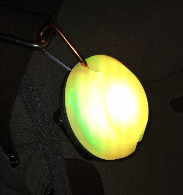
This is an all-in-one, battery powered, single RGBW led module designed to be used with the WLED project. The goal is to provide inexpensive, portable lights for events and DIY use.
Connect 3x AAA batteries and switch on. The USB port can be used to bypass the battery pack for extended usage.
If you want, you can further configure / adjust the light color and effects over WLAN with:
By default the device is looking for a Good Micros WLAN and tries to connect to it.
If it can't find the WLAN it will create an access point which you can connect with your phone or laptop to change the effects and settings.
The AP name is hikari- + the number of your device which is also printed on a sticker in the battery case. The default password for the AP is wled1234.
| issue | cause | solution |
|---|---|---|
| only green works | low battery | replace batteries or connect USB |
| stuck on red | USB connected while powered off | disconnect USB -> switch on -> connect USB |
| stuck on red | button pressed while powering on | power off -> power on without pressing button |
Install WLED via https://install.wled.me/
The switch should be in the power-on position when programming. If WLED installer doesn't allow you to erase the memory, hold the switch while connecting the power (the light should stay red).
After successful flashing remove the device and plug it back in to refresh the serial port. After connecting you have the option to connect the device to WLAN. If it doesn't appear instantly press one of the options from WLED installer and click back to refresh the view.
pin configuration on WLED:
| color | pin |
|---|---|
| red | 16 |
| green | 14 |
| blue | 12 |
| white | 13 |
| Qty | Value | Footprint | References |
|---|---|---|---|
| 12 | 10k | SMT:0603 | NTC1, R5, R6, R7, R8, R9, R10, R11, R12, R14, R16, R17 |
| 11 | 10uF | SMT:0603 | C1, C2, C3, C4, C5, C6, C7, C8, C9, C10, C11 |
| 4 | 0R3 | SMT:0603 | R1, R2, R3, R4 |
| 4 | 4u7 | inductor:CDRH2D11 | L1, L2, L3, L4 |
| 4 | PAM2804AAB010 | SOT:SOT-23-5 | IC1, IC2, IC3, IC4 |
| 3 | 100n | SMT:0603 | C12, C13, C14 |
| 2 | 22p | SMT:0603 | C15, C16 |
| 2 | 5k1 | SMT:0603 | R13, R15 |
| 1 | 12MHZ | xtal:3.2x2.5CXO | x1 |
| 1 | 1x3 | pin_headers:1x3 | CN2 |
| 1 | AP2112K-3.3TRG1 | SOT:SOT-23-5 | IC7 |
| 1 | Battery | pin_headers:Battery_solder-points | BAT1 |
| 1 | CH340G | SOP:SOP-16 | IC6 |
| 1 | ESP-12F | espressif:ESP-12F | IC5 |
| 1 | GSF2301 | SOT:SOT-23 | T1 |
| 1 | JS102011SAQN | buttons:JS102011SAQN | SW2 |
| 1 | LS12W3-T | buttons:LS12W3-T | SW1 |
| 1 | QLSP06RGBXWAJ | SMT:3030_8 | D1 |
| 1 | SK22A | do:DO-214AC | D2 |
| 1 | USB-C | USB:USB4105-GF-A | CN1 |
The 54 most common of 58 parts.
It measures 55.6 × 55.8 mm and has 2 copper layers, 1.6 mm thick.
58 parts, built around the ESP-12F, PAM2804AAB010, CH340G and AP2112K-3.3TRG1. The full list of its parts is on this page, with links to each part's symbol and footprint where PCBKit's library has them.
From the goodmicros/hikari repository on GitHub, at the commit this page was made from: the board is hardware/PCB/hikari.kicad_pcb and its schematic hardware/PCB/LED.kicad_sch. PCBKit opens the board in the browser, with nothing to install.
Its repository states no licence, so its author keeps all rights: ask goodmicros before reusing the design.
second-string/capacitive-touch-button-board-prototype
Protoype hardware and firmware for evaluating different designs of capacitive touch buttons and reverse-mount LEDs


DeanElec/Compact-high-efficiency-illumination-systems-for-in-orbit-microscopy
Presents all data associated with the development of my thesis for a 3rd year final year project at the University of Nottingham, centred around a multimodal condenser free microscope for use on a CubeSat satellite.

renatocampoy/Twitch-LED-Bot
Este projeto permite que você controle um strip de LED NeoPixel via comandos no chat da Twitch, utilizando a placa ESP8266.

OrbitalCommons/gumstick
Gumstick: ESP32 + iCE40UP5K FPGA module (v1 DF40 board-to-board, v2 M.2 gold-finger draft) and its programming carrier. KiCad 10.