2 layers126 × 47.8 mm

 GoodByte-Hardware/BTZ-EndDevice
Low-power wireless sensor board based on the nRF54L15 for BLE Mesh, Thread/Matter and Zigbee
BTZ EndDevice is an open-source printed circuit board by GoodByte-Hardware, from the GoodByte-Hardware/BTZ-EndDevice repository on GitHub, published under the MIT licence. It is a 4-layer board of 35 × 35 mm with 56 parts on 67 nets, routed with 589 tracks and 161 vias.
It is built around the LTR-329ALS-01, BMI270 and AO3401A, with the BAT-HLD-001-TR and 59453-051110ECHLF among its other parts. Its parts include 19 capacitors, 10 resistors, 5 connectors, 4 ICs and 4 inductors. It belongs with the nRF52 and nRF5x boards of this library.


Low-power wireless sensor board based on the nRF54L15 for BLE Mesh, Thread/Matter and Zigbee


BTZ-EndDevice is a battery-powered sensor node designed by GoodByte to compare BLE Mesh, Thread/Matter and Zigbee on the same hardware.
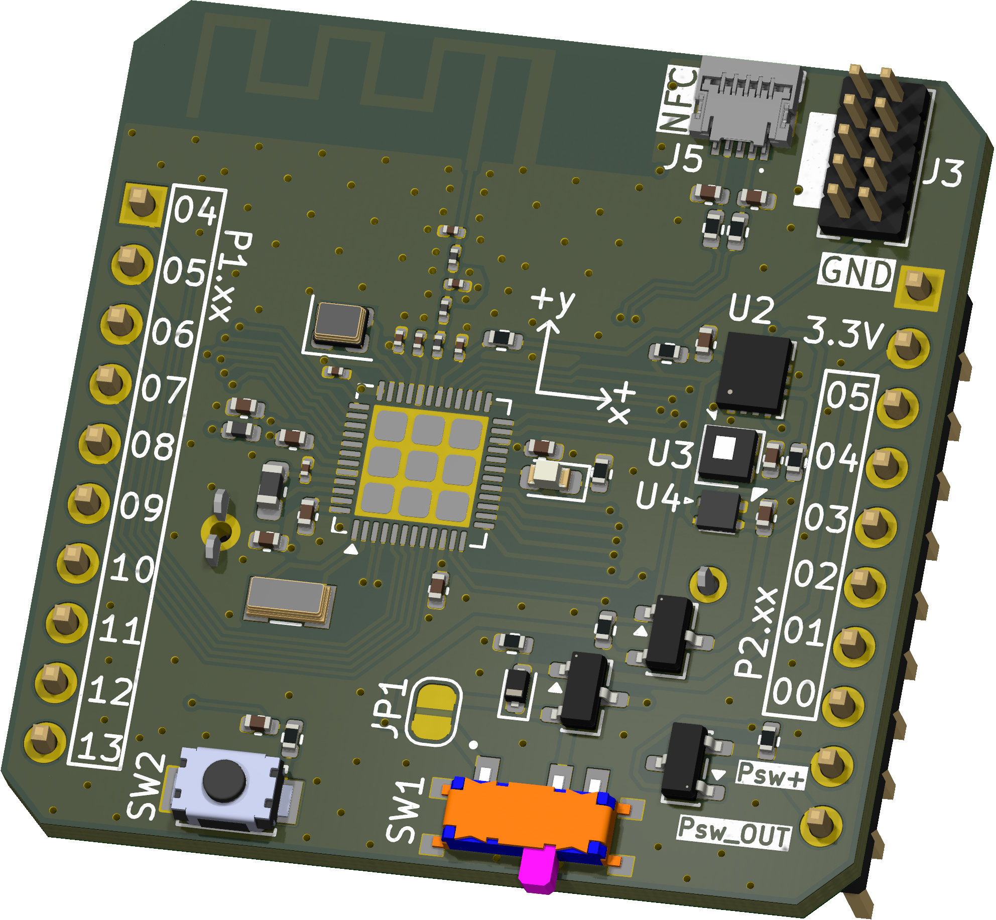
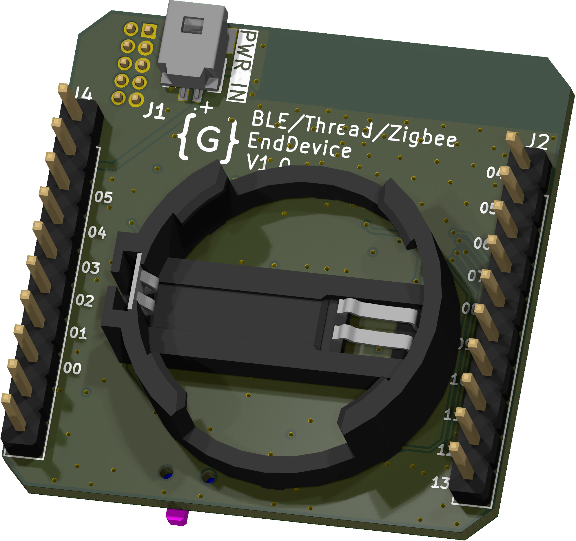
| Parameter | Value |
|---|---|
| SoC | Nordic nRF54L15 |
| Sensors | STS4x (temperature), LTR-329ALS-01 (light), BMI270 (IMU), switchable power |
| Power | CR2032 coin cell or external supply, jumper JP1 for current measurement |
| Interfaces | SWD, GPIO headers, NFC antenna connector, button, LED |
| PCB | 35.0 × 35.0 mm, 4 layers |
All files below are generated by KiBot in CI.
| File | Description |
|---|---|
| Schematic | Full schematic (PDF) |
| BOM (CSV) · BOM (HTML) | Bill of materials |
| Interactive BOM | Component placement viewer (download and open in a browser) |
| Pick and place | Component positions for assembly |
| Assembly drawing | Assembly drawing (PDF) |
| Gerbers | Fabrication files (ZIP) |
| Fabrication drawing | Stackup, drill and fabrication notes (PDF) |
| 3D model | Board model (STEP) |
| Test points | Test point positions and nets (CSV) |
.
├─ 3D                 # STEP model of the board
├─ HTML               # Generated web page with all outputs
├─ Images             # Renders
│
├─ kibot_resources    # External resources for KiBot
│  ├─ colors          # Color theme for KiCad
│  ├─ fonts           # Fonts used in the project
│  ├─ scripts         # External scripts used with KiBot
│  └─ templates       # Templates for KiBot generated reports
│
├─ kibot_yaml         # KiBot YAML config files
├─ KiRI               # KiRI (visual schematic and PCB diff between revisions)
│
├─ Library            # KiCad footprint and symbol libraries
│  ├─ 3D Model        # Component 3D models
│  ├─ Footprint       # Footprint libraries
│  └─ Symbol          # Symbol libraries
│
├─ Logos              # Logos
│
├─ Manufacturing      # Assembly and fabrication documents
│  ├─ Assembly        # Assembly documents (BOM, pick and place, notes)
│ └─ Fabrication # Fabrication documents (Gerbers, drill tables, notes)This project is licensed under the MIT License, see LICENSE.
| Qty | Value | Footprint | References |
|---|---|---|---|
| 6 | 100nF | Capacitor_SMD:C_0402_1005Metric | C2, C3, C5, C13, C15, C16 |
| 3 | AO3401A | Package_TO_SOT_SMD:SOT-23 | Q1, Q2, Q3 |
| 2 | 0R | Resistor_SMD:R_0402_1005Metric | R8, R10 |
| 2 | 10k | Resistor_SMD:R_0402_1005Metric | R4, R5 |
| 2 | 10nF | Capacitor_SMD:C_0402_1005Metric | C7, C18 |
| 2 | 1k | Resistor_SMD:R_0402_1005Metric | R6, R9 |
| 2 | 3,5nH | Inductor_SMD:L_0201_0603Metric | L3, L4 |
| 2 | 300pF | Capacitor_SMD:C_0402_1005Metric | C17, C19 |
| 2 | 470k | Resistor_SMD:R_0402_1005Metric | R1, R7 |
| 2 | Conn_01x10_Pin | Connector_PinHeader_2.54mm:PinHeader_1x10_P2.54mm_Vertical | J2, J4 |
| 1 | 0.3pF | Capacitor_SMD:C_0201_0603Metric | C12 |
| 1 | 1,5pF | Capacitor_SMD:C_0201_0603Metric | C10 |
| 1 | 100nF | Capacitor_SMD:C_0201_0603Metric | C4 |
| 1 | 10μF | Capacitor_SMD:C_0402_1005Metric | C1 |
| 1 | 120R@100MHz | Inductor_SMD:L_0402_1005Metric | FB1 |
| 1 | 1M | Resistor_SMD:R_0402_1005Metric | R2 |
| 1 | 2,2nF | Capacitor_SMD:C_0201_0603Metric | C6 |
| 1 | 2,2μF | Capacitor_SMD:C_0402_1005Metric | C8 |
| 1 | 2,2μF | Capacitor_SMD:C_0201_0603Metric | C9 |
| 1 | 2,7nH | Inductor_SMD:L_0201_0603Metric | L2 |
| 1 | 2pF | Capacitor_SMD:C_0201_0603Metric | C11 |
| 1 | 3,3k | Resistor_SMD:R_0402_1005Metric | R3 |
| 1 | 3,9pF | Capacitor_SMD:C_0201_0603Metric | C14 |
| 1 | 32.768kHz | Crystal:Crystal_SMD_3215-2Pin_3.2x1.5mm | Y2 |
| 1 | 32MHz | Crystal:Crystal_SMD_2016-4Pin_2.0x1.6mm | Y1 |
| 1 | 4,7μH | Inductor_SMD:L_0603_1608Metric | L1 |
| 1 | Antenna | RF_Antenna:Texas_SWRA117D_2.4GHz_Left | AE1 |
| 1 | BMI270 | Package_LGA:Bosch_LGA-14_3x2.5mm_P0.5mm | U2 |
| 1 | CR2032 | Library:CR2032holder | BT1 |
| 1 | Conn_01x02_MountingPin | Library:2035580207 | J1 |
| 1 | Conn_01x05_MountingPin | Library:59453051110ECHLF | J5 |
| 1 | Conn_ARM_JTAG_SWD_10 | Connector_PinHeader_1.27mm:PinHeader_2x05_P1.27mm_Vertical | J3 |
| 1 | D_Schottky | Diode_SMD:D_SOD-523 | D1 |
| 1 | LED | LED_SMD:LED_0603_1608Metric | D2 |
| 1 | LOGO | LOGO | G*** |
| 1 | LTR-329ALS-01 | Library:Lite-On_LTR-329ALS-01 | U4 |
| 1 | STS4X | Library:STS4X | U3 |
| 1 | SW_SPDT | Library:SSSS810701 | SW1 |
| 1 | SW_SPST | Library:SW_TS-1088-AR02016 | SW2 |
| 1 | SolderJumper_2_Open | Jumper:SolderJumper-2_P1.3mm_Open_RoundedPad1.0x1.5mm | JP1 |
| 1 | nRF54L15-QFXX | Package_DFN_QFN:QFN-48-1EP_6x6mm_P0.4mm_EP4.6x4.6mm | U1 |
It measures 35 × 35 mm and has 4 copper layers, 1.66 mm thick.
56 parts, built around the LTR-329ALS-01, BMI270, AO3401A and BAT-HLD-001-TR. The full list of its parts is on this page, with links to each part's symbol and footprint where PCBKit's library has them.
From the GoodByte-Hardware/BTZ-EndDevice repository on GitHub, at the commit this page was made from: the board is BTZ-EndDevice.kicad_pcb and its schematic BTZ-EndDevice.kicad_sch. PCBKit opens the board in the browser, with nothing to install.
Its repository publishes it under the MIT licence: you may reuse it on that licence's terms (keep the author's notice, and for a copyleft licence share your changes alike).


salvatoreraccardi/Energy-Harvesting-DevKit
OBJEX EHDK - Energy harvesting DevKit


unicab369/ESP-MESS
I am building a Wireless Bridge System that can manage multiple devices using a variety of wireless technologies.
