

2 layers99.3 × 78 mm

 gonium/usb-iso-rs48515
I connected a lot of USB-RS485 adapters to my smart meter readout software and wasn't happy. Either the device is cheap and broken or works but is very expensive.
Usb iso rs485 is an open-source printed circuit board by gonium, from the gonium/usb-iso-rs485 repository on GitHub, published under the MIT licence. It is a 2-layer board of 78.2 × 25.1 mm with 39 parts on 31 nets, routed with 252 tracks and 67 vias.
It is built around the FT232RL and IRLML6402. Its parts include 16 capacitors, 7 connectors, 6 resistors, 5 diodes and 2 ICs. It belongs with the interfaces and adapters boards of this library.
I connected a lot of USB-RS485 adapters to my smart meter readout software and wasn't happy. Either the device is cheap and broken or works but is very expensive. The supercheap adaptors from China often provice no ground connection, one worked fine, another one was unstable. Both did not adhere to the USB spec (90mA initial current draw limit). On the other hand, industrial adaptors like the Meilhaus RedCOM USB-COMi-SI or the ADAM 4561 isolate the RS-485 bus from the USB line and work extremely reliable. But they are really expensive.
This project aims to create an adaptor that works well and is reasonably priced. We use the following components:
The first prototype looks like this:
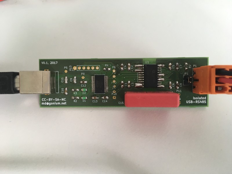
The PCB is too big, and I don't need all those test points any more. Therefore, I have build the second prototype. Please note that the board is slightly smaller, has a different WAGO connector and unpopulated footprints for protection diodes:
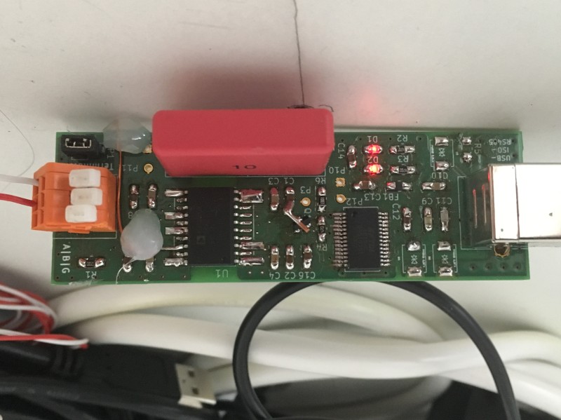
The second prototype works quite well. Unfortunately, the holes for the WAGO connector are too small -- I needed to drill them bigger. While doing so, I destroyed a connection to the "A" pin - the copper wire to the right of the WAGO connector replaces the PCB trace I destroyed. In addition, the footprint for the MOSFET is wrong.
Minor layout changes are needed, but the principle is solid.
The FTDI chip needs to be configured in order to work in this application. Specifically, the following changes need to be written into its EEPROM:
You can use Mark Lord's ft232r_prog to change the EEPROM settings. In order to see the current EEPROM content, use
$ ft232r_prog --verbose --dump --old-vid 0x0403 --old-pid 0x6001In order to set CBUS3 to PwrEN, CBUS4 to TxDEN, high-current-io off and the maximum power consumption to 300 mA, use
$ ft232r_prog --verbose --dump --old-vid 0x0403 --old-pid 0x6001 \
	--cbus3 PwrEn --cbus4 TxDEN --high-current-io off --max-bus-power 300
On Linux I could successfully compile the binary just by typing
make and using it as described above. On Mac OS X, I needed to add
/usr/local to the Makefile. The top two lines now read like this:
CFLAGS = -Wall -O2 -s -Werror -I/usr/local/include
LDFLAGS = -L/usr/local/lib -lusb -lftdi -s
In my case, a FTDI driver claimed the device, preventing the
ft232r_prog command to communicate with the FTDI. You can list the
FTDI-related kernel extensions using
$ kextstat | grep FTDI
	156    0 0xffffff7f83606000 0x8000     0x8000     com.FTDI.driver.FTDIUSBSerialDriver (2.2.16) 0AB01558-B114-9EF2-1CD9-A13CFA557737 <137 55 5 4 3 1>
Then, to unload the driver, use
$ sudo kextunload -b com.FTDI.driver.FTDIUSBSerialDriverfor all FTDI drivers you found.
| Qty | Value | Footprint | References |
|---|---|---|---|
| 7 | 100nF | Capacitors_SMD:C_0805_HandSoldering | C1, C2, C7, C8, C12, C14, C16 |
| 5 | 10nF | Capacitors_SMD:C_0805_HandSoldering | C3, C4, C5, C6, C10 |
| 5 | TST | Measurement_Points:Measurement_Point_Round-TH_Small | P3, P9, P10, P11, P12 |
| 3 | P6SMB 6,8CA | ADM2582E:P6SMB6,8CA | D3, D4, D5 |
| 2 | 470 | Resistors_SMD:R_0805_HandSoldering | R2, R3 |
| 2 | 47pF | Capacitors_SMD:C_0805_HandSoldering | C9, C11 |
| 1 | 0 | Resistors_SMD:R_0805_HandSoldering | R5 |
| 1 | 100k | Resistors_SMD:R_0805_HandSoldering | R6 |
| 1 | 100nF | Capacitors_THT:C_Rect_L26.5mm_W7.0mm_P22.50mm_MKS4 | C15 |
| 1 | 120 | Resistors_SMD:R_0805_HandSoldering | R1 |
| 1 | 4,7uF | Capacitors_SMD:C_0805_HandSoldering | C13 |
| 1 | 4k7 | Resistors_SMD:R_0805_HandSoldering | R4 |
| 1 | ADM2582E | ADM2582E:ADM2582E-SOIC20W-Thermal-Correct | U1 |
| 1 | BLM21PG 600 | Resistors_SMD:R_0805_HandSoldering | FB1 |
| 1 | FT232RL | Housings_SSOP:SSOP-28_5.3x10.2mm_Pitch0.65mm | U2 |
| 1 | Green | LEDs:LED_0805 | D2 |
| 1 | IRLML6402 | ADM2582E:IRLML6402 | Q1 |
| 1 | JUMPER | Pin_Headers:Pin_Header_Straight_1x02_Pitch2.54mm | JP1 |
| 1 | Red | LEDs:LED_0805 | D1 |
| 1 | USB_A | Connectors:USB_B | P2 |
| 1 | WAGO 233-503 | ADM2582E:WAGO233-503 | P1 |


blue-wind-25/JxMake
JxMake is a Java-based, cross-platform build system primarily inspired by the syntax and features of GNU Make, Perforce Jam, and CMake.

lachlanA/eagle-to-kicad
Eagle SCH/LIB to KiCad SCH/LIB ULP conversion script


KaiPereira/Cheetah-MX4-Mini
A powerful yet compact 3D printer motherboard that supports TMC stepsticks, fans, heaters, screens and thermistors
It measures 78.2 × 25.1 mm and has 2 copper layers, 1.6 mm thick.
39 parts, built around the FT232RL and IRLML6402. The full list of its parts is on this page, with links to each part's symbol and footprint where PCBKit's library has them.
From the gonium/usb-iso-rs485 repository on GitHub, at the commit this page was made from: the board is USB-ISO-RS485/USB-ISO-RS485.kicad_pcb. PCBKit opens the board in the browser, with nothing to install.
Its repository publishes it under the MIT licence: you may reuse it on that licence's terms (keep the author's notice, and for a copyleft licence share your changes alike).