
4 layers66 × 60 mm
MainFlightComputer
RockSat-X/RSXVT2026
Our experiment aims to evaluate the use of optical navigation with Commercial-off-the-Shelf (COTS) products for use in spaceflight applications.
72 parts3MIT

 godmar/imuboard-claude
A minimal breakout for the ST LSM6DSV32X 6-axis IMU (±32 g accel, ±4000 dps gyro). The circuit follows the mode 1 connection diagram in ST's datasheet (DS13511, Figure 28, section 7.1).
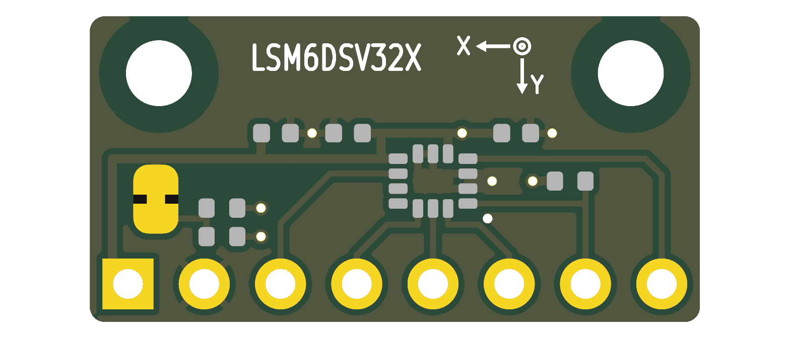
Lsm6dsv32x breakout is an open-source printed circuit board by godmar, from the godmar/imuboard-claude repository on GitHub. It is a 2-layer board of 20.3 × 10.2 mm with 11 parts on 11 nets, routed with 49 tracks and 7 vias.
It is built around the LSM6DSV32X. Its parts include 3 capacitors, 3 resistors, 1 IC and 1 connector. It belongs with the interfaces and adapters boards of this library.
A minimal breakout for the ST LSM6DSV32X 6-axis IMU (±32 g accel, ±4000 dps gyro). The circuit follows the mode 1 connection diagram in ST's datasheet (DS13511, Figure 28, section 7.1).
| Board size | 20.32 × 10.2 mm, 2 layers, 1.6 mm FR4. The width is set by the 8-pin header; the height meets JLCPCB's 10 × 10 mm minimum for assembly. |
| Mounting | Two M2 holes (2.2 mm, non-plated) in the top corners, 15.72 mm apart, 1.9 mm from the top edge. There is no copper within 2 mm of each hole, so a screw head or washer can't short anything. |
| Supply | 3.3 V only. VDD and VDDIO are tied together; there is no regulator or level shifter. |
| Interface | I²C / I3C (default) or SPI (3/4-wire) |
| I²C address | 0x6B (SA0 pulled up by R3). Drive SDO low for 0x6A. |
| Parts | All SMD on top (0402 passives). The header is inserted from the bottom, so its plastic spacer sits under the board. |
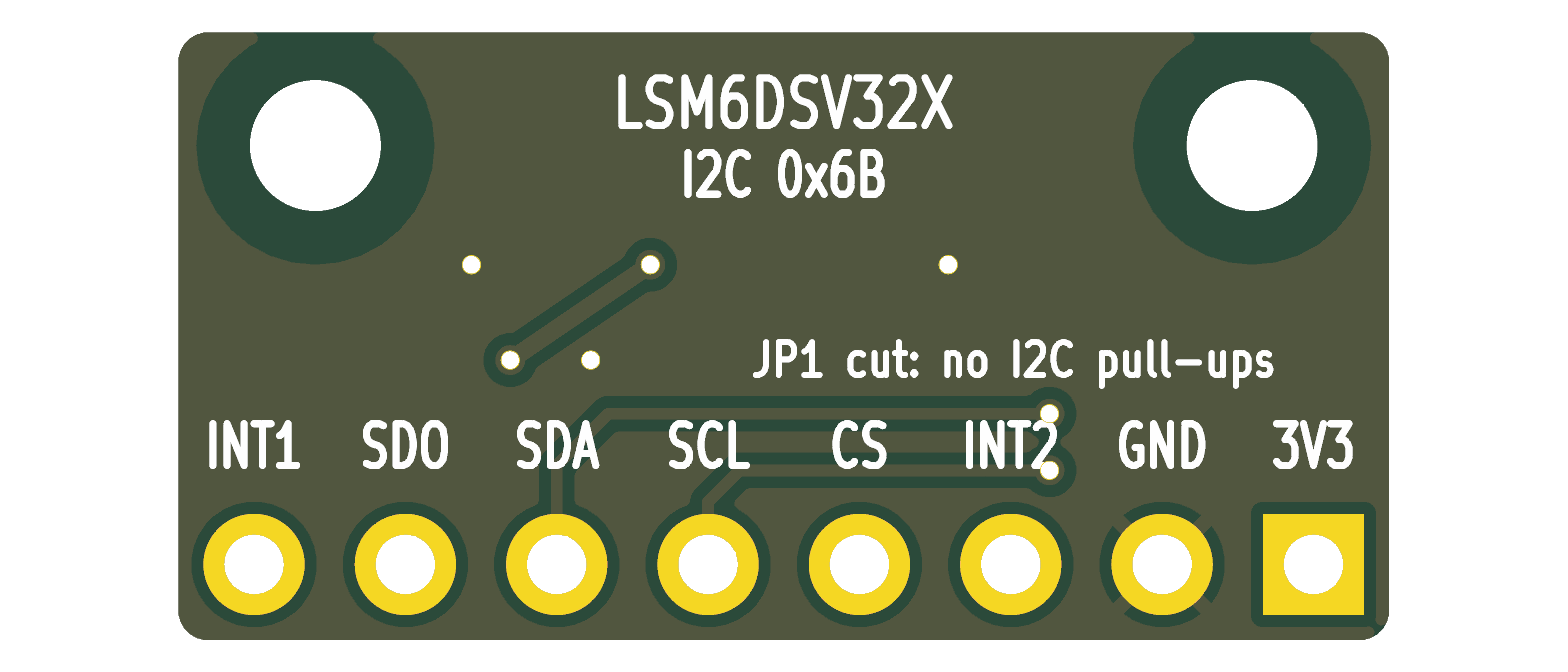
| Pin | 1 | 2 | 3 | 4 | 5 | 6 | 7 | 8 |
|---|---|---|---|---|---|---|---|---|
| Signal | 3V3 | GND | INT2 | CS | SCL / SPC | SDA / SDI | SDO / SA0 | INT1 |
The order follows the ring of IMU pads, so every signal is routed on the top layer without crossings. The pin names are printed on the back silkscreen.
| File | Contents |
|---|---|
lsm6dsv32x_breakout.kicad_pro/.kicad_sch/.kicad_pcb | KiCad 9 project |
imuboard.kicad_sym, sym-lib-table | Project symbol library (LSM6DSV32X symbol) |
fab/lsm6dsv32x_breakout_gerbers.zip | Gerbers + Excellon drill files, ready to upload |
fab/*_bom.csv, fab/*_pos_top.csv | BOM and top-side pick-and-place file (origin: bottom-left corner) |
fab/*_bom_jlcpcb.xlsx, fab/*_cpl_jlcpcb.xlsx (+ .csv) | The same in JLCPCB's assembly upload format, matching their sample files (SMD parts only; J1 is fitted by hand) |
fab/*_schematic.pdf, fab/*_assembly_top.pdf | Printable schematic and assembly drawing |
fab/erc.rpt, fab/drc.rpt | Check reports (0 ERC, 0 DRC, 0 unconnected, 0 schematic-parity issues) |
tools/ | Generator scripts that produce the files above |
The design is generated from scripts. tools/design.py holds the netlist,
tools/gen_schematic.py writes the schematic, and tools/gen_pcb.py does placement,
routing, the GND pours on both layers, and the silkscreen. To rebuild everything, including
the fab outputs and the checks:
./tools/make_fab.shYou can also edit the .kicad_sch / .kicad_pcb files directly in KiCad. Regenerating
overwrites those edits.
These are within standard JLCPCB/PCBWay 2-layer capabilities. The LGA-14 needs stencil and reflow (or hot air) assembly.
The library footprints' silkscreen was moved to the Fab layers because the board is too dense for it. For the same reason the project ignores the "footprint differs from library" DRC check.
| Qty | Value | Footprint | References |
|---|---|---|---|
| 3 | 10k | Resistor_SMD:R_0402_1005Metric | R1, R2, R3 |
| 2 | 100nF | Capacitor_SMD:C_0402_1005Metric | C1, C2 |
| 2 | MountingHole_M2 | MountingHole:MountingHole_2.2mm_M2 | H1, H2 |
| 1 | 4.7uF | Capacitor_SMD:C_0402_1005Metric | C3 |
| 1 | Conn_01x08 | Connector_PinHeader_2.54mm:PinHeader_1x08_P2.54mm_Vertical | J1 |
| 1 | I2C_PU | Jumper:SolderJumper-2_P1.3mm_Bridged_RoundedPad1.0x1.5mm | JP1 |
| 1 | LSM6DSV32X | Package_LGA:LGA-14_3x2.5mm_P0.5mm_LayoutBorder3x4y | U1 |
RockSat-X/RSXVT2026
Our experiment aims to evaluate the use of optical navigation with Commercial-off-the-Shelf (COTS) products for use in spaceflight applications.

PTR-projects/PTR_mini_hardware
Welcome to the KPPTR-hardware repository! This repository contains the design files for the hardware components used in the KPPTR project.

Matheus3007/pcb-lab
PCBs designed entirely as code: Python circuits + KiCad 10 + Freerouting, checked, rendered and ordered assembled from JLCPCB

PTR-projects/PTR_micro_hardware
Welcome to the KPPTR-hardware repository! This repository contains the design files for the hardware components used in the KPPTR project.

punkfab/pcb-corpus
235 real KiCad boards from open-source hardware repositories, prepared as a placement and routing benchmark

google/mozc-devices
Circuit diagrams and firmware source code for Gboard DIY keyboards


FrameworkComputer/ExpansionCards
Reference designs and documentation to create Expansion Cards for the Framework Laptop
It measures 20.3 × 10.2 mm and has 2 copper layers, 1.6 mm thick.
11 parts, built around the LSM6DSV32X. The full list of its parts is on this page, with links to each part's symbol and footprint where PCBKit's library has them.
From the godmar/imuboard-claude repository on GitHub, at the commit this page was made from: the board is lsm6dsv32x_breakout.kicad_pcb and its schematic lsm6dsv32x_breakout.kicad_sch. PCBKit opens the board in the browser, with nothing to install.
Its repository states no licence, so its author keeps all rights: ask godmar before reusing the design.