2 layers65 × 54 mm
Coffeecaller
tiacsys/ecad-coffeecaller
CoffeeCaller. Once a nice office gadget it now evolved to a small development board for the Nordic nRF52840.
85 parts14CERN-OHL-S-2.0
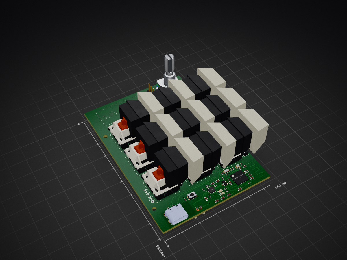
 Gnoled5660/Macrotype1
A fully custom wireless macropad.
Macropad is an open-source printed circuit board by Gnoled5660, from the Gnoled5660/Macrotype repository on GitHub. It is a 4-layer board of 64.2 × 90.9 mm with 62 parts on 84 nets, routed with 745 tracks and 93 vias.
It is built around the NRF52840-QIAA-R, BQ24074RGTR and MCP1700T-3302E/TT(MS), with the TYPE-C-31-M-12 among its other parts. Its parts include 23 capacitors, 11 resistors, 11 switches, 2 ICs and 2 diodes. It belongs with the keyboards and input boards and the nRF52 and nRF5x boards of this library.


This is a fully custom wireless hot swappable macropad with a custom Microcontroller. It has a total of nine fully custom programmable keyswitches and a rotary encoder as well as a 0.91 OLED display. It still remains pretty compact, while having that many components. It's size is approximately 10x6.8x1.6cm. There is a LiPo 3.7V Battery built in, but if you want to charge it, you can simply charge the battery via the USB-C receptacle. The macropad has an IC charger built in. If it is connected to the USB-C port, then the nRF52840 MCU chip, will be directly powered by the external power source, while the battery is being charged. However, if it is not connected to an external power supply, then the chip will be powered by the battery.
I have always wanted to design my own macropad, as it can be quite useful. I wanted to challenge myself a little bit, which is why I didn't choose a regular microcontroller and designed the entire board myself.
It is quite straight forward to assemble everything. As the PCB will be preassembled by JLCPCB, since there are many components that cannot be hand soldered, there is not much to do on the soldering part. It is only necessary to solder the display and the rotary encoder onto the PCB and connect the Battery with the socket. There are four mounting holes on the PCB, that are used to screw screws onto the CAD model. For this project, you only need four M2 screws. It is also recommended to use heated threat inserts, to guarentee more grip.
The main component is the nRF52840, a relatively cheap chip, that is capable of bluetooth low energy. This chip functions as the main processing unit, to handle all the actions that can be done with the board. Another important component is the BQ24074, it is an IC charger that can charge the battery, while still letting power to the MCU. As the battery is a 3.7V LiPo, the voltage always varies between 3.3V and 4.0V. Thats why there is also a Low Dropout Regulator, that convert the voltage to 3.3V.
Using this reference provided by nordic semiconductors, I was able to draw the schematic around the chip.
The PCB is a 4 layer PCB, with the first and fourth layer function as signal transmitting layers. The second layer is a big Ground plane and the third layer is a hybrid layer with signal tracks and Ground planes. The most crucial part of the PCB is the radio frequency part. This part cannot have any tracks or Ground planes above or under it, as any distrubances might change the frequency.
To flash the nRF52840 chip, you have to use a bootloader and connect it physically to the pin sockets on the board. There is a row with SWD sockets. Connect it to these rows and flash the Firmware onto it. You can find it in the folder Firmware. Afterwards, you can simply connect the chip via the USB-C port to a computer and upload the uf2 file, which contains all the keyboard settings and drag the files onto the chip. The keyboard firmware was built with ZMK.
The firmware was built with ZMK. After following the guide of ZMK of how to setup your own ZMK configuration GitHub repo, you have to change the board informations according to your needs. My custom Macropad includes having a rotary encoder, display and a 3x3 Matrix switches. You can find the configurations in detail in the ZMK config file.
The case consists of two different parts. The bottom part has four holes, where heated threat inserts can be inserted. There is a rectangle that stands out a little bit, so that it can be pressed in to the other part.
| Reference | Qty | Links | Value | Footprint | Description | Price |
|---|---|---|---|---|---|---|
| Crystal | 1 | https://jlcpcb.com | 32.768kHz | Crystal:Crystal_SMD_3215-2Pin_3.2x1.5mm | Two pin crystal | See below |
| Crystal | 1 | https://jlcpcb.com | 32MHz | Crystal:Crystal_SMD_2016-4Pin_2.0x1.6mm | Two pin crystal | See below |
| Low Dropout Regulator | 1 | https://jlcpcb.com | MCP1700T-3302E_TT | MCP1700T-3302E_TT:SOT95P237X112-3N | Pwr Sply Func,Voltage Regulator,LDO,SOT-23,PD 369.6mW,VO 3.3V,Regline +/-0.75%/V | Microchip Technology Inc. MCP1700T-3302E/TT | See below |
| IC Charger | 1 | https://jlcpcb.com | BQ24074RGTR | BQ24074RGTR:QFN50P300X300X100-17N | Standalone 1-cell 1.5-A linear battery charger, Power Path, 4.2-V VBAT, 10.5-V OVP and 4.4-V VOUT | See below |
| nRF52840 | 1 | https://jlcpcb.com | NRF52840-QIAA-R | footprints:AQFN-73-1EP_7x7mm_P0.5mm_NRF52840-custom | IC RF TxRx + MCU 802.15.4, Bluetooth Bluetooth v5.0, Thread, Zigbee® 2.4GHz 73-VFQFN Dual Rows, Exposed Pad | See below |
| Rotary Encoder | 1 | https://jlcpcb.com | RotaryEncoder_Switch | Rotary_Encoder:RotaryEncoder_Alps_EC11E-Switch_Vertical_H20mm | Rotary encoder, dual channel, incremental quadrate outputs, with switch | See below |
| Button | 1 | https://jlcpcb.com | SW_Push | Button_Switch_SMD:SW_Push_1P1T_NO_CK_KMR2 | Push button switch, generic, two pins | See below |
| Keyswitch | 9 | https://jlcpcb.com | Keyswitch | Switch_Keyboard_Hotswap_Kailh:SW_Hotswap_Kailh_MX | Push button switch, normally open, two pins, 45° tilted | See below |
| Resistor | 2 | https://jlcpcb.com | 5.1k | Resistor_SMD:R_0402_1005Metric | Resistor | See below |
| Resistor | 3 | https://jlcpcb.com | 10k | Resistor_SMD:R_0402_1005Metric | Resistor | See below |
| Resistor | 1 | https://jlcpcb.com | 47k | Resistor_SMD:R_0402_1005Metric | Resistor | See below |
| Resistor | 1 | https://jlcpcb.com | 0 | Resistor_SMD:R_0402_1005Metric | Resistor | See below |
| Resistor | 1 | https://jlcpcb.com | 5.9k | Resistor_SMD:R_0402_1005Metric | Resistor | See below |
| Resistor | 1 | https://jlcpcb.com | 3.0k | Resistor_SMD:R_0402_1005Metric | Resistor | See below |
| Resistor | 2 | https://jlcpcb.com | 1.5k | Resistor_SMD:R_0402_1005Metric | Resistor | See below |
| Inductor | 1 | https://jlcpcb.com | 4.7nH | Inductor_SMD:L_0402_1005Metric | Inductor | See below |
| USB-C Receptacle | 1 | https://jlcpcb.com | TYPE-C-31-M-12 | TYPE-C-31-M-12:HRO_TYPE-C-31-M-12 | USB Connectors 24 Receptacle 1 8.94*7.3mm RoHS | See below |
| JST Socket | 1 | https://jlcpcb.com | Conn_01x02_Socket | Connector_JST:JST_PH_S2B-PH-K_1x02_P2.00mm_Horizontal | Generic connector, single row, 01x02, script generated | See below |
| LED | 2 | https://jlcpcb.com | LED | LED_SMD:LED_0603_1608Metric | Light emitting diode | See below |
| Unpolarized Capcitor | 1 | https://jlcpcb.com | 820pF | Capacitor_SMD:C_0402_1005Metric | Unpolarized capacitor | See below |
| Unpolarized Capcitor | 1 | https://jlcpcb.com | 1.5pF | Capacitor_SMD:C_0402_1005Metric | Unpolarized capacitor | See below |
| Unpolarized Capcitor | 1 | https://jlcpcb.com | 0.5pF | Capacitor_SMD:C_0402_1005Metric | Unpolarized capacitor | See below |
| Unpolarized Capcitor | 1 | https://jlcpcb.com | 0.8pF | Capacitor_SMD:C_0402_1005Metric | Unpolarized capacitor | See below |
| Unpolarized Capcitor | 1 | https://jlcpcb.com | 100pF | Capacitor_SMD:C_0402_1005Metric | Unpolarized capacitor | See below |
| Unpolarized Capcitor | 2 | https://jlcpcb.com | N.C. | Capacitor_SMD:C_0402_1005Metric | Unpolarized capacitor | See below |
| Unpolarized Capcitor | 1 | https://jlcpcb.com | 1.0uF | Capacitor_SMD:C_0603_1608Metric | Unpolarized capacitor | See below |
| Unpolarized Capcitor | 4 | https://jlcpcb.com | 1uF | Capacitor_SMD:C_0603_1608Metric | Unpolarized capacitor | See below |
| Unpolarized Capcitor | 3 | https://jlcpcb.com | 100nF | Capacitor_SMD:C_0402_1005Metric | Unpolarized capacitor | See below |
| Unpolarized Capcitor | 4 | https://jlcpcb.com | 12pF | Capacitor_SMD:C_0402_1005Metric | Unpolarized capacitor | See below |
| Unpolarized Capcitor | 4 | https://jlcpcb.com | 4.7uF | Capacitor_SMD:C_0603_1608Metric | Unpolarized capacitor | See below |
| 0.91 Display | 1 | https://www.roboter-bausatz.de/p/0.91-oled-display-blau-128-32-ssd1306-i2c-modul-fuer-arduino-raspberry-pi?number=RBS17395&weiche=2&bid=284037-112606-CjwKCAjwxb7RBhA5EiwAQ-AAdFHQgZO50lI-4mJakAwufHefXGeRBqagyHlzbb7zqNV4eCwBOuO-URoCDh8QAvD_BwE%4083&adcref=t.adcell.com%2F | Oled Display 128x32 | 4 | ||
| Hot Swappable Sockets | 50 | https://amazon.com | Kailh CPG151101S11 Hot Swappable PCB Socket | 10 | ||
| PCB with all Components | 1 | https://jlcpcb.com | 5x PCB fully assembled | 110 | ||
| Filament | 40g | 0.5 | ||||
| total | 124 |
| Qty | Value | Footprint | References |
|---|---|---|---|
| 9 | Keyswitch | Switch_Keyboard_Hotswap_Kailh:SW_Hotswap_Kailh_MX | SW1, SW2, SW3, SW4, SW5, SW6, SW7, SW8, SW9 |
| 4 | 12pF | Capacitor_SMD:C_0402_1005Metric | C2, C3, C11, C12 |
| 4 | 1uF | Capacitor_SMD:C_0603_1608Metric | C5, C18, C21, C22 |
| 4 | 4.7uF | Capacitor_SMD:C_0603_1608Metric | C1, C17, C19, C20 |
| 3 | 100nF | Capacitor_SMD:C_0402_1005Metric | C4, C10, C23 |
| 3 | 10k | Resistor_SMD:R_0402_1005Metric | R7, R9, R10 |
| 2 | 1.5k | Resistor_SMD:R_0402_1005Metric | R1, R2 |
| 2 | 5.1k | Resistor_SMD:R_0402_1005Metric | R11, R12 |
| 2 | LED | LED_SMD:LED_0603_1608Metric | D10, D11 |
| 2 | N.C. | Capacitor_SMD:C_0402_1005Metric | C7, C9 |
| 1 | |||
| 1 | 0 | Resistor_SMD:R_0402_1005Metric | R5 |
| 1 | 0.5pF | Capacitor_SMD:C_0402_1005Metric | C14 |
| 1 | 0.8pF | Capacitor_SMD:C_0402_1005Metric | C13 |
| 1 | 1.0uF | Capacitor_SMD:C_0603_1608Metric | C6 |
| 1 | 1.5pF | Capacitor_SMD:C_0402_1005Metric | C15 |
| 1 | 100pF | Capacitor_SMD:C_0402_1005Metric | C8 |
| 1 | 3.0k | Resistor_SMD:R_0402_1005Metric | R3 |
| 1 | 32.768kHz | Crystal:Crystal_SMD_3215-2Pin_3.2x1.5mm | X2 |
| 1 | 32MHz | Crystal:Crystal_SMD_2016-4Pin_2.0x1.6mm | X1 |
| 1 | 4.7nH | Inductor_SMD:L_0402_1005Metric | L1 |
| 1 | 47k | Resistor_SMD:R_0402_1005Metric | R6 |
| 1 | 5.9k | Resistor_SMD:R_0402_1005Metric | R4 |
| 1 | 820pF | Capacitor_SMD:C_0402_1005Metric | C16 |
| 1 | BQ24074RGTR | BQ24074RGTR:QFN50P300X300X100-17N | U2 |
| 1 | Conn_01x02_Socket | Connector_JST:JST_PH_S2B-PH-K_1x02_P2.00mm_Horizontal | J1 |
| 1 | Conn_01x04_Socket | Connector_PinHeader_2.54mm:PinHeader_1x04_P2.54mm_Vertical | Display1 |
| 1 | Conn_01x05_Socket | Connector_PinHeader_2.54mm:PinHeader_1x05_P2.54mm_Vertical | MCU_flash1 |
| 1 | MCP1700T-3302E_TT | MCP1700T-3302E_TT:SOT95P237X112-3N | VR1 |
| 1 | NRF52840-QIAA-R | footprints:AQFN-73-1EP_7x7mm_P0.5mm_NRF52840-custom | U1 |
| 1 | RotaryEncoder_Switch | Rotary_Encoder:RotaryEncoder_Alps_EC11E-Switch_Vertical_H20mm | SW11 |
| 1 | SW_Push | Button_Switch_SMD:SW_Push_1P1T_NO_CK_KMR2 | SW10 |
| 1 | TYPE-C-31-M-12 | TYPE-C-31-M-12:HRO_TYPE-C-31-M-12 | J2 |
The 58 most common of 62 parts.
It measures 64.2 × 90.9 mm and has 4 copper layers, 1.6 mm thick.
62 parts, built around the NRF52840-QIAA-R, BQ24074RGTR, MCP1700T-3302E/TT(MS) and TYPE-C-31-M-12. The full list of its parts is on this page, with links to each part's symbol and footprint where PCBKit's library has them.
From the Gnoled5660/Macrotype repository on GitHub, at the commit this page was made from: the board is Schematic and PCB/Macropad.kicad_pcb and its schematic Schematic and PCB/Macropad.kicad_sch. PCBKit opens the board in the browser, with nothing to install.
Its repository states no licence, so its author keeps all rights: ask Gnoled5660 before reusing the design.
tiacsys/ecad-coffeecaller
CoffeeCaller. Once a nice office gadget it now evolved to a small development board for the Nordic nRF52840.

pierrechevalier83/ferris
A low profile split keyboard designed to satisfy one single use case elegantly

jemmec/legshark
An open source 60% (15 by 5) ortholinear keyboard designed with both flexability and familiarity in mind.


dataehora/beatconfused
A small web studio of fast, elegant, install-free music tools. Every tool is plain HTML, CSS and vanilla JavaScript with the Web Audio API — no build step, no dependencies, no accounts, works offline after first load.

okbrainhq/sMove
Applied to power.kicadsch, compute.kicadsch and smove-r2-main.kicadsch: