4 layers180.3 × 114.9 mm

 GNHua/valve-control4
Use Arduino Uno to control solenoid valves
Valve testing is an open-source printed circuit board by GNHua, from the GNHua/valve-control repository on GitHub, published under the MIT licence. It is a 2-layer board of 73.7 × 55.9 mm with 49 parts on 63 nets, routed with 222 tracks and 12 vias.
It is built around the HCPL2731 and 74HC595. Its parts include 16 resistors, 13 connectors, 8 transistors, 5 ICs and 4 diodes. It belongs with the audio and music boards and the AVR (ATmega, ATtiny) boards of this library.


Use Arduino Uno to control solenoid valves.
Follow the steps below to set up your own valve control station.
Details can be found on page 215-221 in Clippard Full-line Catalog
| Top Layer | Bottom Layer |
|---|---|
 |  |
| Part | Label on PCB | Qty. (per PCB) | Purchase |
|---|---|---|---|
| Shift register, SN74HC595N | plug on the DIP socket (U1) | 1 | link |
| Optoisolator, HCPL 2731 | plug on the DIP sockets (U2-U5) | 4 | link |
| Resistor, 2.32 kΩ, package 0805 | R1-R16 | 16 | link |
| Common anode diode | D1-D4 | 4 | link |
| PMOS | Q1-Q8 | 8 | link |
| 1 uF capacitor, package 0805, voltage rating 10V | C1 | 1 | link |
| DIP socket, 2x8 | U1 | 1 | link |
| DIP socket, 2x4 | U2-U5 | 4 | link |
| Stacking headers | J2-J4, H1, H2 | 1 | link |
| Connector, Molex 50212-8000 | N/A | 18 | link |
| Connector housing, Molex 0873690200 | N/A | 9 | link |
| JST header, Molex 0894010210 | J5-J13 | 9 | link |
| 2.5 mm barrel jack, 5A max, CUI PJ-057BH | J1 | 1 for each setup | link |
Download zip and extract all files.
arduino_valve_control.ino in arduino_valve_control folder with Arduino IDETools > PortUpload (the right arrow at the top left corner)platforms/windows/setup.bat$ bash <path to>/platforms/macosx/setup.sh(ADD photos of top and bottom layer after soldering)
Solder all the components according to the table above. The surface mount components are soldered to the bottom layer, while the rest are mounted on the top layer.
In the table above, the stacking headers contains the following headers.
| Stacking Header | Label on PCB | Qty. |
|---|---|---|
| 1 x 10 | cut out a 1x2 for J4 | 1 |
| 1 x 8 | H1, H2 | 2 |
| 1 x 6 | 2 | |
| 2 x 3 | J2+J3 | 1 |
Because the JST headers at J11 and J12 block H3 on the top layer, I would do the following:
Each setup only needs one barrel jack to connect to a 12 V power supply. The barrel jack can be soldered on any one of the boards.
(The images shown below are all taken for the previous PCB design, which is marginally different from the current design.)
After soldering, plug the shift register and optoisolators into their corresponding DIP sockets. Refer to the following image for their orientation.
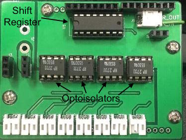
| Data Pin | Serial Input/Output |
|---|---|
 |  |
In the images above, there are 4 boards stacked on an Arduino Uno.
Each board provides 8 solenoid valve connectors, and the current design supports up to 6 boards.
Before putting the boards together, the data pins on all boards except Board 1 must be bent or removed.
This is because the data pin connects to the serial input of shift register.
On Board 1, the shift register receives data from the Arduino directly.
For the Board 2-n, their shift registers must have its serial input connected to the serial output of board right beneath it.
| Qty | Value | Footprint | References |
|---|---|---|---|
| 16 | 2.32k | Resistors_SMD:R_0805_HandSoldering | R1, R2, R3, R4, R5, R6, R7, R8, R9, R10, R11, R12, R13, R14, R15, R16 |
| 9 | Conn_01x02 | Pin_Headers:Pin_Header_Straight_1x02_Pitch2.00mm | J5, J6, J7, J8, J9, J10, J11, J12, J13 |
| 8 | Q_PMOS_GSD | TO_SOT_Packages_SMD:SOT-23W_Handsoldering | Q1, Q2, Q3, Q4, Q5, Q6, Q7, Q8 |
| 4 | D_Schottky_x2_ACom_KKA | TO_SOT_Packages_SMD:SOT-23_Handsoldering | D1, D2, D3, D4 |
| 4 | HCPL2731 | Housings_DIP:DIP-8_W7.62mm_Socket | U2, U3, U4, U5 |
| 2 | Conn_01x04 | Pin_Headers:Pin_Header_Straight_1x03_Pitch2.54mm | J2, J3 |
| 1 | 1u | Capacitors_Tantalum_SMD:CP_Tantalum_Case-A_EIA-3216-18_Hand | C1 |
| 1 | 74HC595 | Housings_DIP:DIP-16_W7.62mm | U1 |
| 1 | Arduino_Uno_Shield | Arduino:Arduino_Uno_Shield | XA1 |
| 1 | Barrel_Jack | Connectors:BARREL_JACK | J1 |
| 1 | Conn_01x02 | Pin_Headers:Pin_Header_Straight_1x02_Pitch2.54mm | J4 |
The 48 most common of 49 parts.
It measures 73.7 × 55.9 mm and has 2 copper layers, 1.6 mm thick.
49 parts, built around the HCPL2731 and 74HC595. The full list of its parts is on this page, with links to each part's symbol and footprint where PCBKit's library has them.
From the GNHua/valve-control repository on GitHub, at the commit this page was made from: the board is pcb_layout/valve_testing.kicad_pcb. PCBKit opens the board in the browser, with nothing to install.
Its repository publishes it under the MIT licence: you may reuse it on that licence's terms (keep the author's notice, and for a copyleft licence share your changes alike).

Tinkerforge/evse-bricklet
This Bricklet together with the ESP32 Brick the RS485 Bricklet and the NFC Bricklet form the hardware used in the WARP Charger

Tinkerforge/industrial-dual-ac-in-bricklet
Industrial Dual AC In Bricklet ==============================


tardate/LittleArduinoProjects
a collection of "Little Electronic & Arduino Projects", most involving electronics or an Arduino in one way or another!

ChrisChrisLoLo/beyblock20
The magnetic, modular, 20-key macropad that can join together to form an ortholinear board

slu4coder/Minimal-64x4-Home-Computer
My DIY TTL home computer with VGA and PS/2 and 4x the processing power of a Commodore C64 or Apple II.

electroniceel/protoboard
Advanced protoboard layout with 1.27mm pitch for smd parts