
2 layers80 × 54.7 mm

 gnGeovane/CNC-Plotter1
Arquivos e códigos relacionados à CNC Plotter
Shield arduino is an open-source printed circuit board by gnGeovane, from the gnGeovane/CNC-Plotter repository on GitHub, published under the MIT licence. It is a 2-layer board of 69.1 × 53.8 mm with 31 parts on 41 nets, routed with 273 tracks and 14 vias.
It is built around the 74HC595. Its parts include 19 connectors, 4 resistors, 2 diodes, 1 capacitor and 1 IC. It belongs with the robots and motor control boards of this library.
Aqui você encontrará os arquivos necessários para fazer uma CNC Plotter e controlá-la.
Todos os códigos e a biblioteca para motores de passo foram feitos do zero, linha-a-linha, especificamente para este projeto. As versões mais recentes do código para o arduino incluem suporte para:
Para a comunicação do computador com o arduino para o envio do G-CODE do desenho, foi feito um G-CODE Sender do zero, programado no processing 4. Este arquivo, quando executado no compilador processing, cria uma interface gráfica simples mostrando os comandos de controle da CNC, como:
Também foi criado um app em Kotlin no Android Studio que funciona de forma similar ao programa G-CODE Sender do item anterior. Porém, o diferencial do app para celular é a possibilidade de controlar a máquina à distância via Bluetooth.
Para criar o arquivo de coordenadas (G-CODE) de uma imagem para desenhá-la, é necessário utilizar o software InksCape (gratuito) ou Autodesk ArtCAM (Pago). Caso queira plotar um circuito em uma PCB, poderá converter arquivos Gerber(.gbr) e Excellon(.drl) em G-CODE utilizando o software de código aberto FlatCAM.
Desenhando ícone do app (controle por Bluetooth com app)
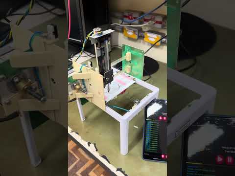
Desenhando um avião (controle via porta serial)

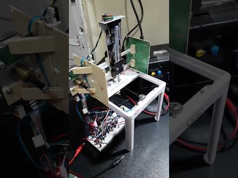
short - Desenhando um touro (Controle via porta serial)
| Qty | Value | Footprint | References |
|---|---|---|---|
| 4 | MountingHole_3.2mm | Arduino_MountingHole:MountingHole_3.2mm | MH1, MH2, MH3, MH4 |
| 3 | Drivers VCC | Connector:FanPinHeader_1x03_P2.54mm_Vertical | J18, J18, J18 |
| 2 | 1k | Resistor_THT:R_Axial_DIN0207_L6.3mm_D2.5mm_P7.62mm_Horizontal | R2, R4 |
| 2 | LED | LED_THT:LED_D5.0mm | D1, D2 |
| 1 | 0.1uF | Capacitor_THT:C_Disc_D4.3mm_W1.9mm_P5.00mm | C4 |
| 1 | 1.8k | Resistor_THT:R_Axial_DIN0207_L6.3mm_D2.5mm_P7.62mm_Horizontal | R3 |
| 1 | 4,7k | Resistor_THT:R_Axial_DIN0207_L6.3mm_D2.5mm_P7.62mm_Horizontal | R1 |
| 1 | 74HC595 | Package_DIP:DIP-16_W7.62mm | U1 |
| 1 | Analog | Connector_PinSocket_2.54mm:PinSocket_1x06_P2.54mm_Vertical | J3 |
| 1 | Analog | Connector_PinHeader_2.54mm:PinHeader_1x06_P2.54mm_Vertical | J14 |
| 1 | Bluetooth | Connector_PinHeader_2.54mm:PinHeader_1x04_P2.54mm_Horizontal | J10 |
| 1 | Digital/PWM | Connector_PinSocket_2.54mm:PinSocket_1x08_P2.54mm_Vertical | J4 |
| 1 | Digital/PWM | Connector_PinHeader_2.54mm:PinHeader_1x08_P2.54mm_Vertical | J16 |
| 1 | Digital/PWM | Connector_PinSocket_2.54mm:PinSocket_1x10_P2.54mm_Vertical | J2 |
| 1 | Digital/PWM | Connector_PinHeader_2.54mm:PinHeader_1x10_P2.54mm_Vertical | J15 |
| 1 | FAN | Connector_PinHeader_2.54mm:PinHeader_1x02_P2.54mm_Vertical | J8 |
| 1 | I2C | Connector_PinHeader_2.54mm:PinHeader_1x04_P2.54mm_Vertical | J11 |
| 1 | MXF | Connector_PinHeader_2.54mm:PinHeader_1x04_P2.54mm_Vertical | J19 |
| 1 | MYF | Connector_PinHeader_2.54mm:PinHeader_1x04_P2.54mm_Vertical | J12 |
| 1 | MZF | Connector_PinHeader_2.54mm:PinHeader_1x04_P2.54mm_Vertical | J20 |
| 1 | Power | Connector_PinSocket_2.54mm:PinSocket_1x08_P2.54mm_Vertical | J1 |
| 1 | Power | Connector_PinHeader_2.54mm:PinHeader_1x08_P2.54mm_Vertical | J13 |
| 1 | Sensores | Connector_PinHeader_2.54mm:PinHeader_2x06_P2.54mm_Vertical | J17 |
| 1 | Vdrive | TerminalBlock:TerminalBlock_bornier-2_P5.08mm | J5 |

tardate/LittleArduinoProjects
a collection of "Little Electronic & Arduino Projects", most involving electronics or an Arduino in one way or another!

ChrisChrisLoLo/beyblock20
The magnetic, modular, 20-key macropad that can join together to form an ortholinear board

slu4coder/Minimal-64x4-Home-Computer
My DIY TTL home computer with VGA and PS/2 and 4x the processing power of a Commodore C64 or Apple II.

electroniceel/protoboard
Advanced protoboard layout with 1.27mm pitch for smd parts

TobleMiner/DC-UPS
A small DC UPS, designed to keep small appliances like consumer network equipment running during power outages


It measures 69.1 × 53.8 mm and has 2 copper layers, 1.6 mm thick.
31 parts, built around the 74HC595. The full list of its parts is on this page, with links to each part's symbol and footprint where PCBKit's library has them.
From the gnGeovane/CNC-Plotter repository on GitHub, at the commit this page was made from: the board is PCB's para a CNC Plotter/shield/shield arduino.kicad_pcb and its schematic PCB's para a CNC Plotter/Drivers CNC/shield arduino.kicad_sch. PCBKit opens the board in the browser, with nothing to install.
Its repository publishes it under the MIT licence: you may reuse it on that licence's terms (keep the author's notice, and for a copyleft licence share your changes alike).