2 layers57 × 55.2 mm
LogicAnalyzer
gusmanb/logicanalyzer
24 channel, 100Msps logic analyzer hardware and software
10 parts5.1kGPL-3.0

 GMMan/openreset8
Standalone card resetter
Carrier board is an open-source printed circuit board by GMMan, from the GMMan/openreset repository on GitHub. It is a 2-layer board of 40 × 68.9 mm with 10 parts on 38 nets, routed with 44 tracks and 3 vias.
Its parts include 1 resistor, 1 IC, 1 diode and 1 connector. It belongs with the computers and single-board computers boards and the RP2040 boards of this library.
This project is designed to allow you to easily reset your card with a standalone device. No need to connect to a computer to use (in fact you can't read the card from a computer using this device).
Supported cards:
It is easy to build your own OpenReset from loose parts.
To build your own OpenReset, you will need the following:
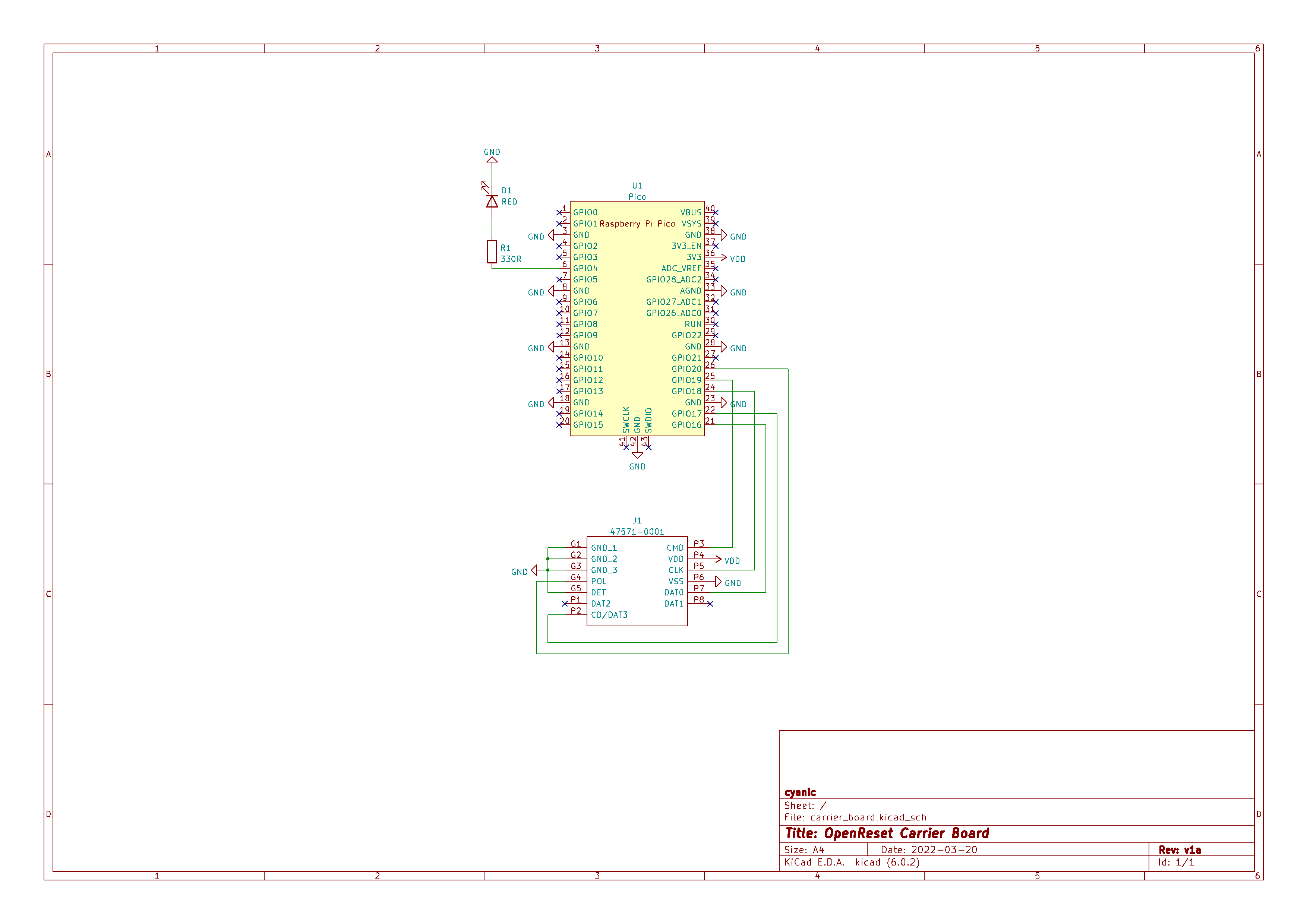
3V3 pin on the Pico to your positive power rail and any GND
pin to your ground rail.DAT0 or MISODAT3 or CSCLK or CLKCMD or MOSIAlternatively, you can have a carrier board fabbed and solder the Pi Pico to it along with a few other components.
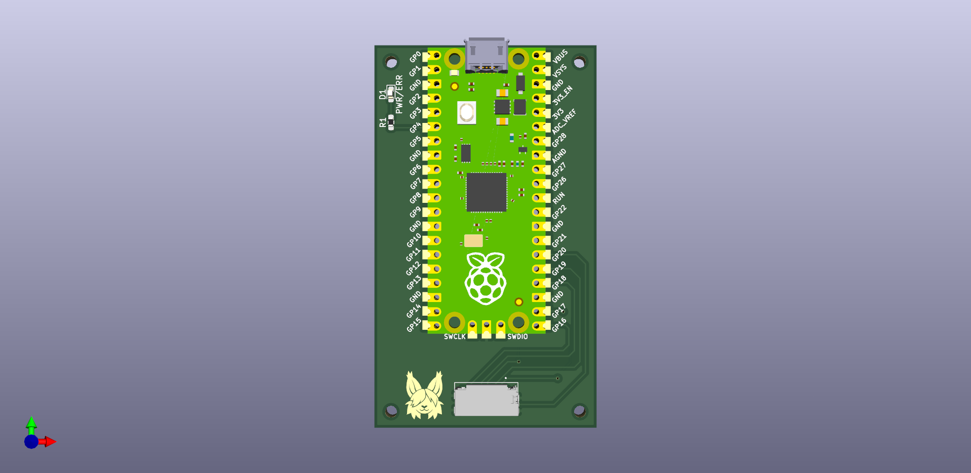
Board design files are in the carrier_board directory. Gerbers are available in the carrier_board/gerber directory, and are available as a ZIP file.
U1) (Official resellers)J1) (Digikey)D1)R1) (for current limiting the LED; please calculate the
value based on your LED's datasheet, but in general a 330Ω resistor will work)BOOTSEL button on your Pico, then plug the Pico into your
computer while still holding the button. You can release the button
once the Pico shows up on your computer as a USB drive.MicroPython (Raspberry Pi Pico).File -> Save copy... from the menu strip. Click Raspbery Pi Pico when asked
where to save to. Type in the name of the file in the File name box,
and click OK.The board is easy to use. All you have to do is insert your card and the device will automatically perform the erase. The red LED will always be on to indicate power, and the green LED on the Pi Pico will light up when the erase is in progress. After the erase is completed, the green LED will extinguish. If there is an error, the red LED will blink off a number of times to indicate the error.
There are messages printed to UART if you need more info on troubleshooting. I suggest loading the code up in Thonny and checking the shell for the messages.
Warning: TamaSma Card locking area is embedded in the card header. By nature of SPI NOR flash, changing this data will involve erasing the sector, so there is a risk of breaking the data if the connection is bad. Therefore, be careful when plugging in a TamaSma Card to plug it in firmly.
If your are using a DIY build and your microSD breakout board does not have a card detect pin, then you can use the switch/button alternative. Flip the switch or hold the button after you have inserted a card. The process will complete and the red LED will flash if there are errors. If you are using a button, make sure to hold the button until the error has finished blinking, if applicable. Flip the switch again or release the button before inserting the next card.
| Qty | Value | Footprint | References |
|---|---|---|---|
| 1 | 330R | Library:R_0603_1608Metric_Pad0.98x0.95mm_HandSolder | R1 |
| 1 | 47571-0001 | Library:475710001 | J1 |
| 1 | LOGO | carrier_board:cyanic_logo | G*** |
| 1 | Pico | Library:RPi_Pico_SMD_TH | U1 |
| 1 | RED | Library:LED_0603_1608Metric_Pad1.05x0.95mm_HandSolder | D1 |
The 5 most common of 10 parts.
It measures 40 × 68.9 mm and has 2 copper layers, 1.6 mm thick.
10 parts. The full list of its parts is on this page, with links to each part's symbol and footprint where PCBKit's library has them.
From the GMMan/openreset repository on GitHub, at the commit this page was made from: the board is carrier_board/carrier_board.kicad_pcb and its schematic carrier_board/carrier_board.kicad_sch. PCBKit opens the board in the browser, with nothing to install.
Its repository states no licence, so its author keeps all rights: ask GMMan before reusing the design.
gusmanb/logicanalyzer
24 channel, 100Msps logic analyzer hardware and software

byrantech/laptop
anyon_e, a highly integrated, high end, open source laptop. Attempt the impossible.

joeycastillo/Sensor-Watch
A board replacement for the classic Casio F-91W wristwatch


OLIMEX/OLINUXINO
OLINUXINO is Open Source / Open Hardware, low cost from EUR 24 Linux Industrial grade Single Board Computer capable to operate -25+85C

rusefi/rusefi
rusefi - GPL internal combustion engine control unit

VoronDesign/Voron-Hardware
Cool Hardware designed by the Voron Design group

hoglet67/RGBtoHDMI
Bare-metal Raspberry Pi project that provides pixel-perfect sampling of Retro Computer RGB/YUV video and conversion to HDMI