2 layers54 × 45 mm

 gloutchov/Sonometer-A1
Analog battery-powered sound level indicator, 60–95 dB(A) · Rilevatore sonoro analogico a batteria
Sonometer A1 is an open-source printed circuit board by gloutchov, from the gloutchov/Sonometer-A1 repository on GitHub, published under the Apache-2.0 licence. It is a 2-layer board of 100 × 80 mm with 97 parts on 68 nets, routed with 833 tracks and 39 vias.
It is built around the AD8436ARQZ, CMC-9745-44P and SS14. Its parts include 44 resistors, 21 capacitors, 11 diodes, 7 ICs and 1 connector.




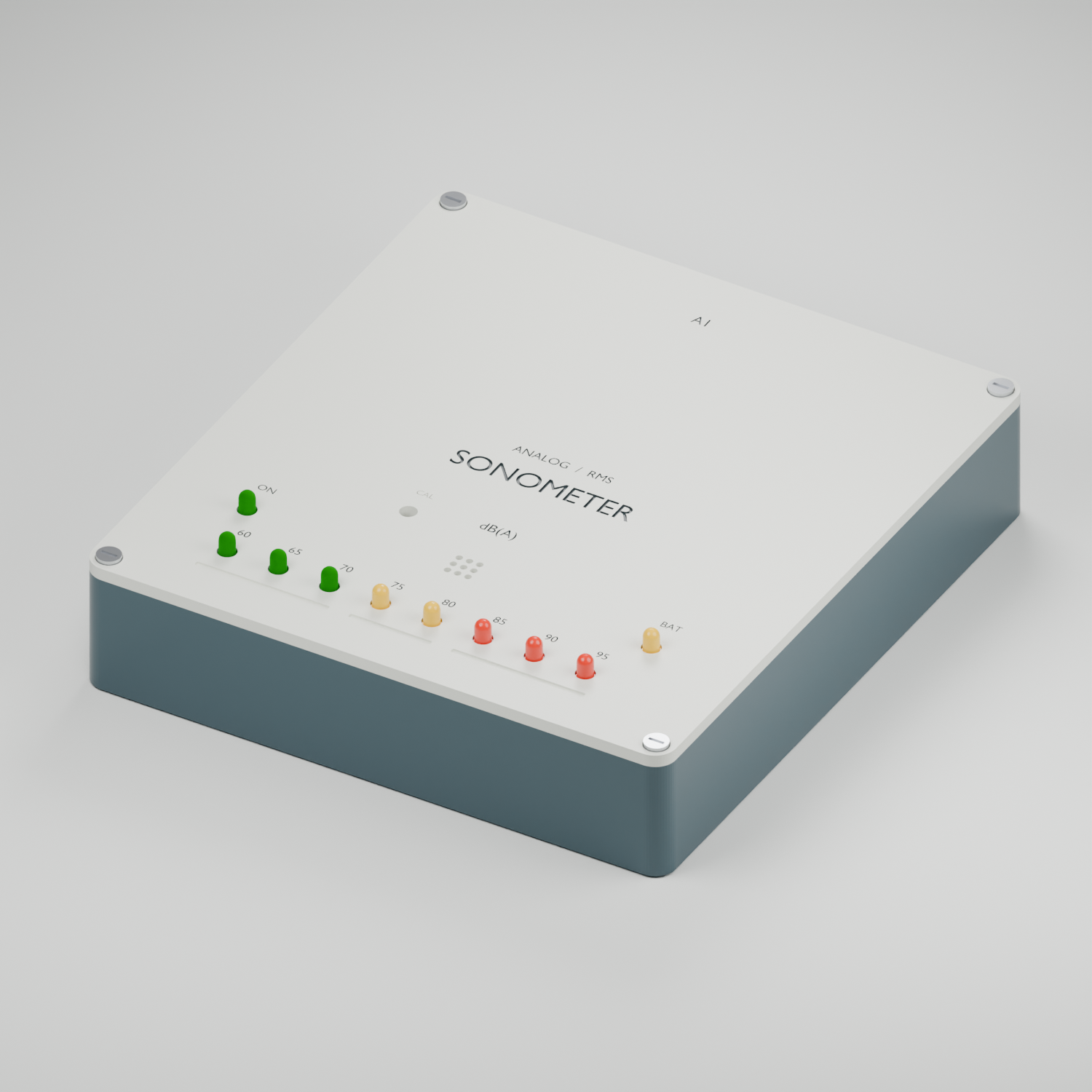
Sonometer A1 è un rilevatore sonoro analogico alimentato da una pila da 9 V. Una barra cumulativa di otto LED visualizza livelli di progetto da 60 a 95 dB(A), a passi di 5 dB:
Il percorso del segnale comprende microfono, preamplificatore, filtro di ponderazione A, convertitore RMS reale, comparatori e barra LED. Il dispositivo non usa microprocessori, firmware o componenti programmabili.
[!WARNING] Stato: prototipo da montare, tarare e collaudare. I file di progetto e produzione sono completi, ma non è stato ancora costruito o misurato un esemplare fisico. Sonometer A1 non è un fonometro certificato né un dosimetro e non calcola la dose cumulativa o i picchi impulsivi. La sicurezza dell'esposizione dipende anche dalla durata: il colore dei LED non certifica che un'esposizione sia sicura.
L'intero progetto è stato realizzato da ChatGPT ASTRA, partendo dal seguente prompt:
@KiCad @Blender Voglio realizzare un rilevatore di suoni 'forti'. Il circuito
deve essere realizzato con componenti discreti, senza microprocessore o elementi
programmabili, deve avere una serie di led colorati che indichino in dB
l'intensità dei suoni rilevati. Vorrei che i led fossero verdi per i dB che sono
adatti all'udito umano, gialli quando si arriva a livelli limite, rossi quando
sono dannosi se mantenuti a lungo. Mi serve lo schema elettrico, la bill of
material, lo sbroglio del pcb, i files gerber, un 3d del pcb, e una scatolina che
lo conterrà. Usa kicad per la realizzazione di schemi e circuito, e blender per
la scatolina.
Lo scopo del progetto è valutare se un'AI sia in grado di sviluppare un dispositivo hardware completo a partire da un prompt non troppo dettagliato. Il risultato mi ha stupito. Mostra ancora alcuni limiti, fra cui schemi elettrici talvolta “non convenzionali” e un posizionamento dei componenti sul PCB poco ottimizzato, ma resta stupefacente considerando che l'intero sviluppo, dal prompt al “prodotto pronto per essere campionato”, è avvenuto in soli 59 minuti.
| Percorso | Contenuto |
|---|---|
KiCad/ | Schema gerarchico, PCB, simboli, impronte e modelli 3D per KiCad 10 |
Meccanica/ | Sorgente Blender, contenitore STL, PCB STEP/GLB e distanziale LED |
Produzione/Gerber/ | Gerber X2 e forature Excellon PTH/NPTH pronti per il preventivo |
Documentazione/ | Manuale, schema, disegno di montaggio e distinte base |
Verifiche/ | Rapporti ERC/DRC, controlli meccanici e calcoli di filtro e soglie |
Anteprime/ | Rendering del PCB e del contenitore |
MANIFEST_SHA256.txt | Hash SHA-256 dei file distribuiti |
KiCad/Sonometer_A1.kicad_pro con KiCad 10.0 o successivo.Meccanica/Sonometer_A1.blend con Blender 5.2 o successivo.Manuale_Sonometer_A1.pdf per montaggio, taratura, collaudo e limiti.Schema_elettrico.pdf e il Montaggio_PCB.pdf.Il PCB misura 100 × 80 mm ed è progettato per FR-4 da 1,6 mm, due strati e rame da 35 µm (1 oz). Le piste nominali sono da 0,25 mm, l'isolamento minimo è 0,20 mm e le via sono da 0,60/0,30 mm. I dati di produzione includono maschera su entrambi i lati e serigrafia frontale; non richiedono impedenza controllata e non includono stencil perché è previsto l'assemblaggio manuale.
Per ordinare e assemblare:
Produzione/Gerber/ al produttore seguendo ISTRUZIONI_PCB.txt. Le coordinate sono assolute e i file non vanno specchiati.BOM_acquisti.csv per l'ordine dei componenti, BOM.csv per i riferimenti sul PCB e BOM_meccanica.csv per contenitore, minuteria e cablaggio.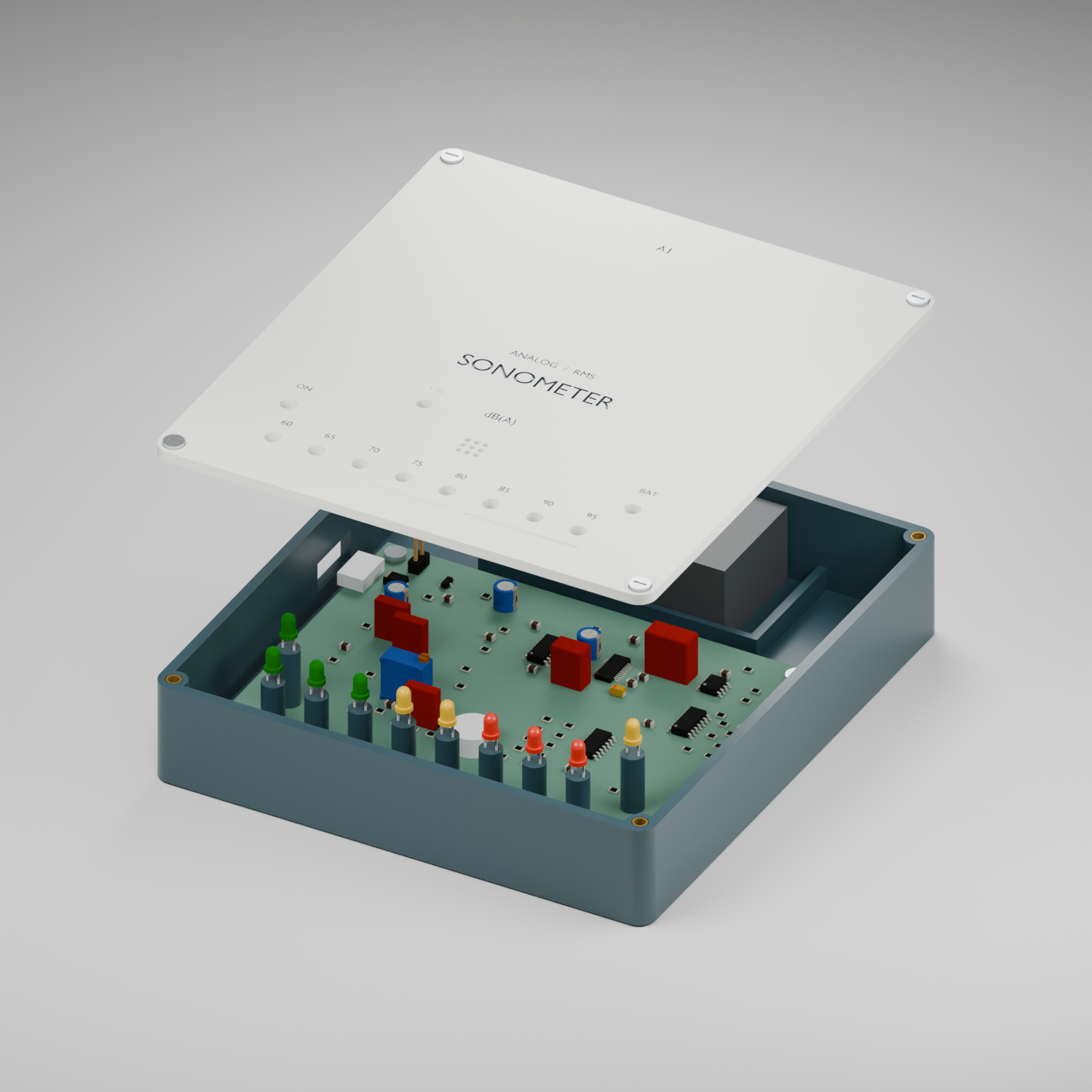
Con il contenitore chiuso, applicare un tono da 1 kHz e usare un fonometro di riferimento tarato. A 94,0 dB regolare RV1, accessibile dal foro CAL, finché TP2 misura 1,7825 V DC rispetto a TP3. Verificare quindi tutte le soglie e la risposta in frequenza del prototipo. Se si accende il LED BAT, sostituire la pila e ignorare l'indicazione in dB. La procedura completa è nel manuale.
Questi controlli sono digitali e non sostituiscono il collaudo elettrico, acustico e meccanico di un esemplare fisico.
Salvo dove indicato diversamente, il progetto è distribuito con licenza Apache License 2.0. Le impronte standard e i modelli STEP provenienti dalle librerie KiCad conservano la licenza CC BY-SA 4.0 e la relativa eccezione per progetti elettronici e file generati. Consultare ATTRIBUZIONI.md per i dettagli.
Sonometer A1 is an analog, 9 V battery-powered sound level indicator. A cumulative eight-LED bar displays design levels from 60 to 95 dB(A) in 5 dB steps:
The signal path comprises a microphone, preamplifier, A-weighting filter, true-RMS converter, comparators, and LED bar. The device has no microprocessor, firmware, or programmable component.
[!WARNING] Status: prototype to be assembled, calibrated, and tested. The design and production files are complete, but no physical unit has yet been built or measured. Sonometer A1 is neither a certified sound level meter nor a dosimeter, and it does not calculate cumulative dose or impulse peaks. Exposure safety also depends on duration: the LED color does not certify that an exposure is safe.
The entire project was created by ChatGPT ASTRA, starting from the following prompt (translated from the original Italian):
@KiCad @Blender I want to build a detector for “loud” sounds. The circuit must
be made with discrete components, without a microprocessor or programmable
elements, and it must have a series of colored LEDs that indicate the detected
sound intensity in dB. I would like the LEDs to be green for dB levels suitable
for human hearing, yellow when approaching limit levels, and red when harmful
if sustained for a long time. I need the schematic, bill of materials, PCB
layout, Gerber files, a 3D model of the PCB, and a small enclosure for it. Use
KiCad to design the schematics and circuit, and Blender for the enclosure.
The purpose of this project is to evaluate whether an AI can develop a complete hardware device from a prompt that is not overly detailed. The result surprised me. It still shows some limitations, including occasionally “unconventional” schematics and component placement on the PCB that is not fully optimized, yet the outcome is remarkable considering that the entire development process—from the prompt to a “product ready to be prototyped”—took only 59 minutes.
| Path | Contents |
|---|---|
KiCad/ | Hierarchical schematic, PCB, symbols, footprints, and 3D models for KiCad 10 |
Meccanica/ | Blender source, STL enclosure, STEP/GLB PCB, and LED spacer |
Produzione/Gerber/ | Gerber X2 and separate PTH/NPTH Excellon drill files ready for quotation |
Documentazione/ | Manual, schematic, assembly drawing, and bills of materials |
Verifiche/ | ERC/DRC reports, mechanical checks, and filter/threshold calculations |
Anteprime/ | PCB and enclosure renders |
MANIFEST_SHA256.txt | SHA-256 hashes for the distributed files |
KiCad/Sonometer_A1.kicad_pro with KiCad 10.0 or later.Meccanica/Sonometer_A1.blend with Blender 5.2 or later.Manuale_Sonometer_A1.pdf for assembly, calibration, testing, and limitations. The manual is in Italian.Schema_elettrico.pdf and Montaggio_PCB.pdf for quick reference.The PCB is 100 × 80 mm and is designed for 1.6 mm FR-4, two layers, and 35 µm (1 oz) copper. Nominal tracks are 0.25 mm, minimum clearance is 0.20 mm, and vias are 0.60/0.30 mm. The manufacturing data includes solder mask on both sides and front silkscreen. No controlled impedance is required, and no stencil files are included because the board is intended for hand assembly.
To order and assemble it:
Produzione/Gerber/ to the board manufacturer, following ISTRUZIONI_PCB.txt. Coordinates are absolute; do not mirror the files.BOM_acquisti.csv to purchase components, BOM.csv for PCB references, and BOM_meccanica.csv for the enclosure, hardware, and wiring.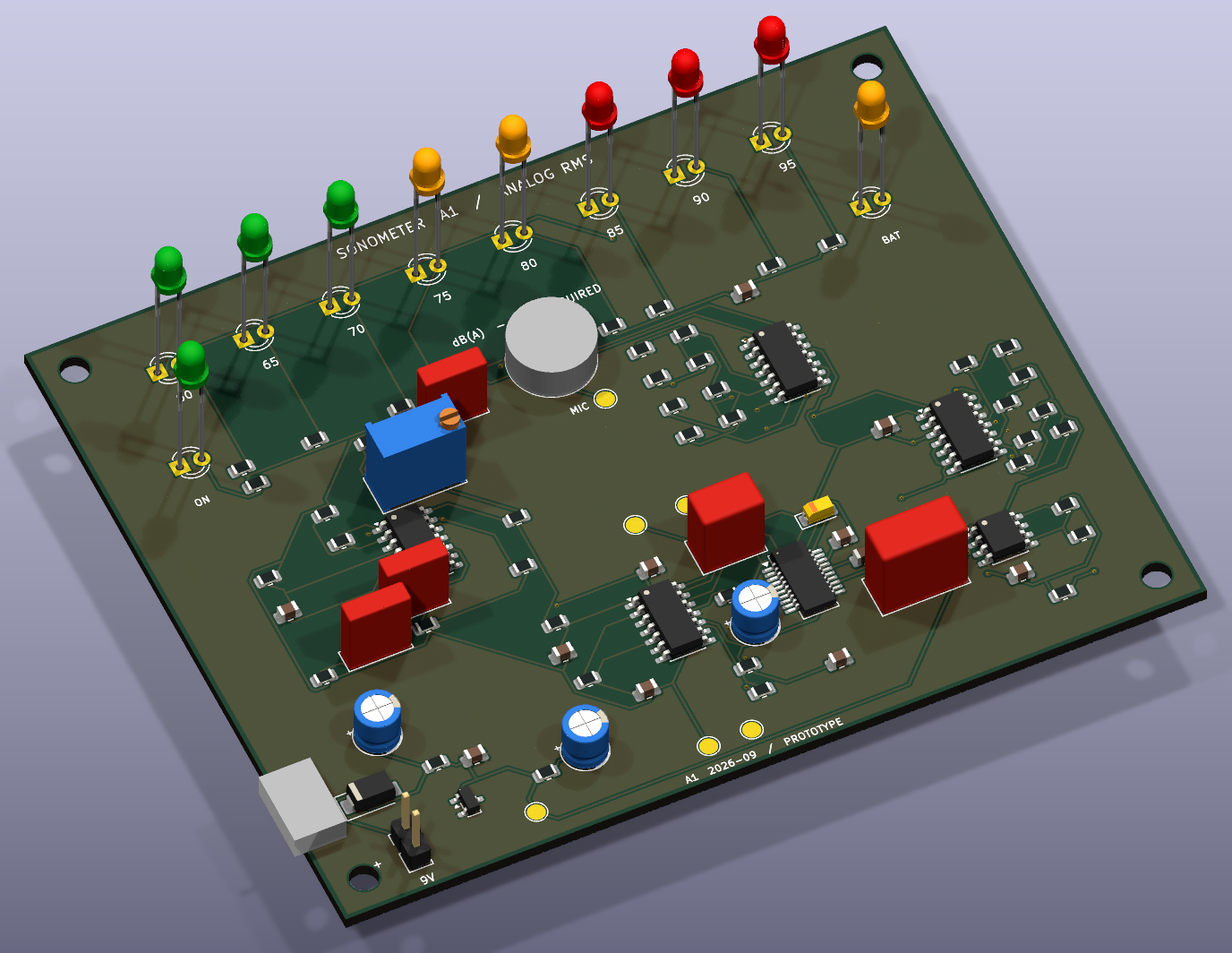
With the enclosure closed, apply a 1 kHz tone and use a calibrated reference sound level meter. At 94.0 dB, adjust RV1 through the CAL access hole until TP2 reads 1.7825 V DC relative to TP3. Then verify every threshold and the prototype's frequency response. If the BAT LED turns on, replace the battery and disregard the dB indication. See the manual for the complete procedure.
These are digital checks and do not replace electrical, acoustic, and mechanical testing of a physical unit.
Unless otherwise stated, this project is licensed under the Apache License 2.0. Standard footprints and STEP models derived from the KiCad libraries retain their CC BY-SA 4.0 license and the associated exception for electronic designs and generated files. See ATTRIBUZIONI.md for details.
| Qty | Value | Footprint | References |
|---|---|---|---|
| 9 | 10.0k | Sonometer:R_0805_2012Metric | R14, R40, R41, R42, R43, R44, R45, R46, R47 |
| 9 | 3.30k | Sonometer:R_0805_2012Metric | R20, R21, R22, R23, R24, R25, R26, R27, R52 |
| 7 | 100n | Sonometer:C_0805_2012Metric | C13, C16, C17, C18, C19, C20, C21 |
| 4 | M3 | Sonometer:MountingHole_3.2mm_M3 | H1, H2, H3, H4 |
| 3 | 100n | Sonometer:C_Rect_L7.2mm_W2.5mm_P5.00mm | C4, C5, C6 |
| 2 | 13.0k | Sonometer:R_0805_2012Metric | R12, R13 |
| 2 | 1n | Sonometer:C_0805_2012Metric | C8, C9 |
| 2 | 1u | Sonometer:C_0805_2012Metric | C2, C15 |
| 2 | 2.00k | Sonometer:R_0805_2012Metric | R10, R11 |
| 2 | 47u | Sonometer:CP_Radial_D5.0mm_P2.00mm | C1, C3 |
| 2 | 75.0k | Sonometer:R_0805_2012Metric | R4, R34 |
| 2 | LM339BIDR | Sonometer:SOIC-14_3.9x8.7mm_P1.27mm | U4, U5 |
| 2 | OPA4197IDR | Sonometer:SOIC-14_3.9x8.7mm_P1.27mm | U1, U2 |
| 1 | 1.00k | Sonometer:R_0805_2012Metric | R5 |
| 1 | 1.50k | Sonometer:R_0805_2012Metric | R1 |
| 1 | 100 | Sonometer:R_0805_2012Metric | R2 |
| 1 | 10M | Sonometer:R_0805_2012Metric | R16 |
| 1 | 10n | Sonometer:C_0805_2012Metric | C7 |
| 1 | 10u | Sonometer:CP_EIA-3216-18_Kemet-A | C12 |
| 1 | 10u | Sonometer:CP_Radial_D5.0mm_P2.00mm | C11 |
| 1 | 110k | Sonometer:R_0805_2012Metric | R50 |
| 1 | 14.7k | Sonometer:R_0805_2012Metric | R8 |
| 1 | 140k | Sonometer:R_0805_2012Metric | R33 |
| 1 | 16.5k | Sonometer:R_0805_2012Metric | R36 |
| 1 | 1u | Sonometer:C_Rect_L10.0mm_W5.0mm_P5.00mm_P7.50mm | C14 |
| 1 | 2.20k | Sonometer:R_0805_2012Metric | R3 |
| 1 | 20.0k | Sonometer:R_0805_2012Metric | R6 |
| 1 | 20k CAL | Sonometer:Potentiometer_Bourns_3296W_Vertical | RV1 |
| 1 | 21.5k | Sonometer:R_0805_2012Metric | R9 |
| 1 | 255k | Sonometer:R_0805_2012Metric | R32 |
| 1 | 30.0k | Sonometer:R_0805_2012Metric | R15 |
| 1 | 37.4k | Sonometer:R_0805_2012Metric | R35 |
| 1 | 4.99k | Sonometer:R_0805_2012Metric | R37 |
| 1 | 464k | Sonometer:R_0805_2012Metric | R31 |
| 1 | 470n | Sonometer:C_Rect_L7.2mm_W4.5mm_P5.00mm | C10 |
| 1 | 6.80k | Sonometer:R_0805_2012Metric | R53 |
| 1 | 60 dBA VERDE | Sonometer:LED_D3.0mm | D1 |
| 1 | 65 dBA VERDE | Sonometer:LED_D3.0mm | D2 |
| 1 | 70 dBA VERDE | Sonometer:LED_D3.0mm | D3 |
| 1 | 75 dBA GIALLO | Sonometer:LED_D3.0mm | D4 |
| 1 | 76.8k | Sonometer:R_0805_2012Metric | R7 |
| 1 | 80 dBA GIALLO | Sonometer:LED_D3.0mm | D5 |
| 1 | 82.5k | Sonometer:R_0805_2012Metric | R51 |
| 1 | 825k | Sonometer:R_0805_2012Metric | R30 |
| 1 | 85 dBA ROSSO | Sonometer:LED_D3.0mm | D6 |
| 1 | 90 dBA ROSSO | Sonometer:LED_D3.0mm | D7 |
| 1 | 95 dBA ROSSO | Sonometer:LED_D3.0mm | D8 |
| 1 | AD8436ARQZ | Sonometer:QSOP-20_3.9x8.7mm_P0.635mm | U3 |
| 1 | AUDIO_A | Sonometer:TestPoint_Pad_D2.0mm | TP1 |
| 1 | BAT 9V | Sonometer:PinHeader_1x02_P2.54mm_Vertical | J1 |
| 1 | BAT LOW | Sonometer:LED_D3.0mm | D9 |
| 1 | CMC-9745-44P | Sonometer:Mic_9.7mm_P2.54 | MK1 |
| 1 | GND | Sonometer:TestPoint_Pad_D2.0mm | TP3 |
| 1 | LEVEL | Sonometer:TestPoint_Pad_D2.0mm | TP2 |
| 1 | LM393BIDR | Sonometer:SOIC-8_3.9x4.9mm_P1.27mm | U6 |
| 1 | LM4040A-3.0 | Sonometer:SOT-23 | U7 |
| 1 | MIC | Sonometer:TestPoint_Pad_D2.0mm | TP6 |
| 1 | ON / OFF | Sonometer:SW_SPDT_CK_JS102011SAQN | SW1 |
| 1 | POWER | Sonometer:LED_D3.0mm | D10 |
| 1 | SS14 | Sonometer:D_SMA | D11 |
| 1 | VMID | Sonometer:TestPoint_Pad_D2.0mm | TP5 |
| 1 | VREF3 | Sonometer:TestPoint_Pad_D2.0mm | TP4 |
It measures 100 × 80 mm and has 2 copper layers, 1.6 mm thick.
97 parts, built around the AD8436ARQZ, CMC-9745-44P and SS14. The full list of its parts is on this page, with links to each part's symbol and footprint where PCBKit's library has them.
From the gloutchov/Sonometer-A1 repository on GitHub, at the commit this page was made from: the board is KiCad/Sonometer_A1.kicad_pcb and its schematic KiCad/Alimentazione.kicad_sch. PCBKit opens the board in the browser, with nothing to install.
Its repository publishes it under the Apache-2.0 licence: you may reuse it on that licence's terms (keep the author's notice, and for a copyleft licence share your changes alike).

JGAguado/Smart_Plant
The Smart Plant is a board that can be plugged directly on the soil, close to the plant, that allows the measurement of the environment (soil moisture, environment temperature & illuminance), and presents the…

ugcs/ddc
Drone Show Software is software designed for drone shows, allowing flight path planning as well as control of dozens of drones simultaneously in a synchronized manner.

eddyem/stm32samples
Code samples and ready projects based on bare-metal STM32


execuc/u2if
USB to interfaces implementing MicroPython "machine" module functionalities on a computer.

ZeroPhone/ZeroPhone-PCBs
PCB files for ZeroPhone - for gerbers and schematics, go to "Releases" tab!