

2 layers74.2 × 42 mm
Cablight project
gkuegler/undercabinet-lighting-ctrl
Click here to purchase one from the Adafruit shop
16 parts

 gkuegler/undercabinet-lighting-ctrl
Click here to purchase one from the Adafruit shop
Adafruit QT Py ESP32-S3 is an open-source printed circuit board by gkuegler, from the gkuegler/undercabinet-lighting-ctrl repository on GitHub. It is a 4-layer board of 17.8 × 20.7 mm with 49 parts on 35 nets, routed with 402 tracks and 39 vias.
It is built around the AP2112K-3.3 and NSR0320MW2. Its parts include 20 capacitors, 5 resistors, 4 crystals, 3 diodes and 2 transistors. It belongs with the ESP32 boards of this library.
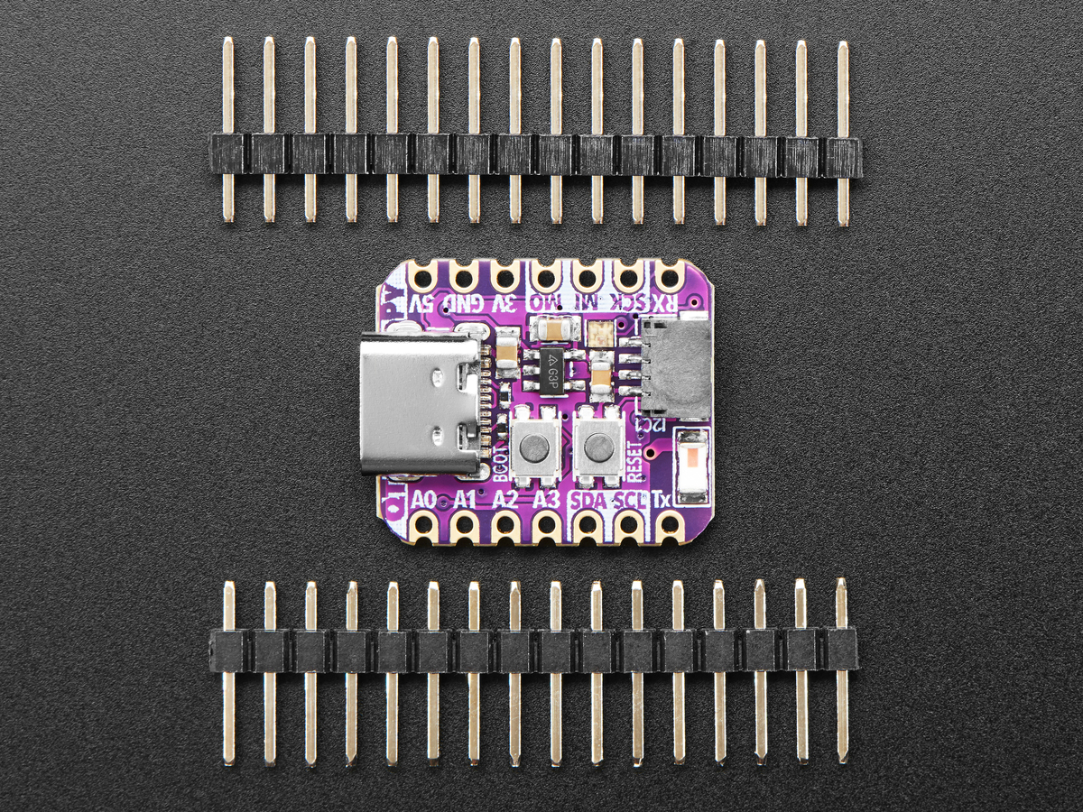
Click here to purchase one from the Adafruit shop
PCB files for the Adafruit QT Py ESP32-S3 WiFi Dev Board.
Format is EagleCAD schematic and board layout
The ESP32-S3 has arrived in QT Py format - and what a great way to get started with this powerful new chip from Espressif! With dual 240 MHz cores, WiFi and BLE support, and native USB, this QT Py is great for powering your IoT projects.
The ESP32-S3 is a highly-integrated, low-power, 2.4 GHz Wi-Fi System-on-Chip (SoC) solution that now has WiFi and BLE support, built-in native USB as well as some other interesting new technologies like Time of Flight distance measurements. With its state-of-the-art power and RF performance, this SoC is an ideal choice for a wide variety of application scenarios relating to the Internet of Things (IoT), wearable electronics, and smart homes.
With native USB and 8 MB Flash this board will let you upgrade your existing ESP32 projects. Native USB means it can act like a keyboard or a disk drive, and no external USB-to-Serial converter required. WiFi and BLE mean it's awesome for IoT projects.
OLEDs! Inertial Measurement Units! Sensors a-plenty. All plug-and-play thanks to the innovative chainable design: SparkFun Qwiic-compatible STEMMA QT connectors for the I2C bus so you don't even need to solder! Just plug in a compatible cable and attach it to your MCU of choice, and you’re ready to load up some software and measure some light. Seeed Grove I2C boards will also work with this adapter cable.
Pinout and shape are Seeed Xiao compatible, with castellated pads so you can solder it flat to a PCB. In addition to the QT connector, we also added an RGB NeoPixel (with controllable power pin to allow for ultra-low-power usage), a reset button (great for restarting your program or entering the bootloader), and a button on GPIO 0 for entering the ROM bootloader or for user input
The ESP32-S3 has a dual-core 240 MHz chip, so it is comparable to ESP32's dual-core. However, there is no Bluetooth Classic support, only Bluetooth LE. This chip is a great step up from the earlier ESP32-S2! This ESP32-S3 chip we are using on the QT Py comes with 8 MB flash and no PSRAM, but it does have 512KB of SRAM so its fine for use with CircuitPython support as long as massive buffers are not needed. It's also great for use in ESP-IDF or with Arduino support.
Adafruit invests time and resources providing this open source design, please support Adafruit and open-source hardware by purchasing products from Adafruit!
Designed by Limor Fried/Ladyada for Adafruit Industries.
Creative Commons Attribution/Share-Alike, all text above must be included in any redistribution. See license.txt for additional details.
| Qty | Value | Footprint | References |
|---|---|---|---|
| 7 | 1uF | _0402NO | C2, C3, C5, C13, C15, C19, C20 |
| 6 | 0.1uF | _0402NO | C4, C10, C11, C12, C14, C16 |
| 3 | 22uF | 0805-NO | C1, C6, C8 |
| 2 | 1X07_CASTEL | JP1, JP3 | |
| 2 | NSR0320 | SOD-323_MINI | D1, D2 |
| 2 | 16pF | _0402NO | C17, C18 |
| 2 | 5.1K | _0402NO | R5, R6 |
| 2 | FIDUCIAL_1MM | FIDUCIAL_1MM | U$6, U$8 |
| 2 | TBD | _0402NO | C7, C9 |
| 2 | TPB1,27 | B1,27_385 | SWC1, SWC2 |
| 1 | TESTPOINT_MINUS_1X3MM | GND0 | |
| 1 | QTPYS3_BOT | U$11 | |
| 1 | TESTPOINT_PLUS_1X3MM | VBAT0 | |
| 1 | QTPY_ESP32_TOP | U$7 | |
| 1 | PCBFEAT-REV-040 | U$12 | |
| 1 | 0 | _0402NO | R3 |
| 1 | 0 ohm | _0402 | L2 |
| 1 | 10K | _0402NO | R1 |
| 1 | 1Meg | _0402NO | R17 |
| 1 | 2.4 GHz Antenna | ANT_2450AT18B100 | X1 |
| 1 | 2nH | _0402NO | L1 |
| 1 | 40MHz | CRYSTAL_2X1.6 | Y1 |
| 1 | AP2112K-3.3 | SOT23-5 | U1 |
| 1 | BOOT0 | BTN_KMR2_4.6X2.8 | Q1 |
| 1 | ESP32-S3QFN54 | QFN56_7X7 | X2 |
| 1 | STEMMA_I2C_QTSKINNY | JST_SH4_SKINNY | CONN1 |
| 1 | USB TYPE C | USB_C_CUSB31-CFM2AX-01-X | X6 |
| 1 | WS2812B_SK6805_1515 | SK6805_1515 | LED1 |
| 1 | reset | BTN_KMR2_4.6X2.8 | Q2 |
gkuegler/undercabinet-lighting-ctrl
Click here to purchase one from the Adafruit shop


Hugoyhu/corgikeychain
Corgi "keychain" LilyPad with ATSAMD21E18

Hugoyhu/Hack-Club-Sticker-Development-Boards
"Sticker" dev boards.

d4vid-le/qt-py-esp32-s2-experiment
A personal, non-production experiment: reconstruct the Adafruit QT Py ESP32-S2 (Product 5325, Rev C) in KiCad from the authoritative Eagle source, measuring how accurately an AI agent can do it — and documenting every…

h7ga40/RP2040_Logicool_K275_PCB
Replace PCB of Logitech K275 keyboard with RP2040

michaelpmurphy14/AirQ-automation
using ESP32C3 chip to collect and analyze air quality data

SreeniEadara/ATesp32
esp32s3 board that has an identical footprint and similar pinout to the ATmega32.

syn-ack-zack/SkeletonKey
SkeletonKey is the firmware for the Hackers Teaching Hackers 2022 Goonies badge. It starts as a seven-part hardware CTF and, once unlocked, becomes a small ESP8266 infrared and Wi-Fi experimentation toolkit.
It measures 17.8 × 20.7 mm and has 4 copper layers, 1.6 mm thick.
49 parts, built around the AP2112K-3.3 and NSR0320MW2. The full list of its parts is on this page, with links to each part's symbol and footprint where PCBKit's library has them.
From the gkuegler/undercabinet-lighting-ctrl repository on GitHub, at the commit this page was made from: the board is kicad/cablight-project/external part symbols, footprints & step files/Adafruit-QT-Py-ESP32-S3-PCB-main/Adafruit QT Py ESP32-S3.kicad_pcb and its schematic kicad/cablight-project/cablight-project.kicad_sch. PCBKit opens the board in the browser, with nothing to install.
Its repository states no licence, so its author keeps all rights: ask gkuegler before reusing the design.