2 layers100 × 80 mm
Meganecan gw
Barbedx/MeganeCAN
ESP32-based CAN-bus companion for Renault Megane 2 infotainment displays.
68 parts3

 ginomcfino/smart-fan-controller
Dual-fan controller with temperature sensing, tachometer monitoring, overtemperature alarm, and manual override. Designed in KiCad.
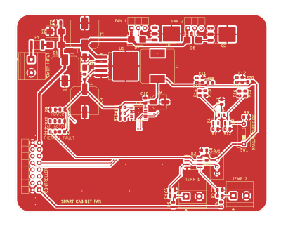
Smart Cabinet Fan is an open-source printed circuit board by ginomcfino, from the ginomcfino/smart-fan-controller repository on GitHub. It is a 2-layer board of 95 × 75 mm with 61 parts on 38 nets, routed with 247 tracks and 44 vias.
It is built around the LM2596S-3.3, LTC1840CGN#TRPBF and LMV393, with the BAT54C, SS56 and SMBJ33A among its other parts. Its parts include 23 resistors, 12 capacitors, 11 diodes, 6 connectors and 3 ICs.


A dual-fan controller design with temperature inputs, tachometer conditioning, a hardware overtemperature alarm, and manual override.
Status: CAD design study
This is my manually developed circuit and PCB design. Component libraries, manufacturer models, and other supplied assets retain their original attribution.
Open hardware/Smart_Cabinet_Fan.kicad_pro with KiCad 10 and its standard symbol, footprint, and 3D model libraries.
| Qty | Value | Footprint | References |
|---|---|---|---|
| 7 | 10k | Resistor_SMD:R_0805_2012Metric | R3, R4, R7, R8, R9, R18, R20 |
| 7 | 1k | Resistor_SMD:R_0805_2012Metric | R1, R2, R17, R19, R21, R22, R23 |
| 6 | 100nF | Capacitor_SMD:C_0805_2012Metric | C2, C5, C6, C7, C8, C10 |
| 5 | 100k | Resistor_SMD:R_0805_2012Metric | R10, R11, R12, R13, R16 |
| 3 | BAT54C | Package_TO_SOT_SMD:SOT-23 | D4, D5, D6 |
| 3 | SS56 | Diode_SMD:D_SMB | D1, D7, D8 |
| 2 | 100R | Resistor_SMD:R_0805_2012Metric | R14, R15 |
| 2 | 10nF | Capacitor_SMD:C_0805_2012Metric | C11, C12 |
| 2 | 4.7k | Resistor_SMD:R_0805_2012Metric | R5, R6 |
| 2 | 60V Logic-Level NMOS | Package_TO_SOT_SMD:TO-252-3_TabPin2 | Q1, Q2 |
| 1 | 100uF 50V | Capacitor_SMD:CP_Elec_10x10 | C3 |
| 1 | 10k Pot | Potentiometer_THT:Potentiometer_Bourns_3296W_Vertical | RV1 |
| 1 | 10uF | Capacitor_SMD:CP_Elec_5x5.4 | C9 |
| 1 | 220uF 10V | Capacitor_SMD:CP_Elec_10x7.7 | C4 |
| 1 | 220uF 50V | Capacitor_SMD:CP_Elec_10x12.5 | C1 |
| 1 | 68uH | Inductor_SMD:L_Bourns_SRR1260 | L1 |
| 1 | CONTROLLER_INTERFACE | Connector_PinHeader_2.54mm:PinHeader_2x08_P2.54mm_Horizontal | J6 |
| 1 | FAN ACTIVITY LED | LED_SMD:LED_0805_2012Metric | D10 |
| 1 | Fan 1 | Connector_PinHeader_2.54mm:PinHeader_1x03_P2.54mm_Horizontal | J4 |
| 1 | Fan 2 | Connector_PinHeader_2.54mm:PinHeader_1x03_P2.54mm_Horizontal | J5 |
| 1 | LM2596S-3.3 | Package_TO_SOT_SMD:TO-263-5_TabPin3 | U1 |
| 1 | LMV393 | Package_SO:SOIC-8_3.9x4.9mm_P1.27mm | U2 |
| 1 | LTC1840CGNTR | Package_SO:SSOP-16_3.9x4.9mm_P0.635mm | U3 |
| 1 | NTC_SENSOR_1 | TerminalBlock_Phoenix:TerminalBlock_Phoenix_MKDS-1,5-2_1x02_P5.00mm_Horizontal | J2 |
| 1 | NTC_SENSOR_2 | TerminalBlock_Phoenix:TerminalBlock_Phoenix_MKDS-1,5-2_1x02_P5.00mm_Horizontal | J3 |
| 1 | POWER LED | LED_SMD:LED_0805_2012Metric | D9 |
| 1 | Polyfuse | Fuse:Fuse_1812_4532Metric | F1 |
| 1 | SMBJ33A | Diode_SMD:D_SMB | D2 |
| 1 | SS36 | Diode_SMD:D_SMA | D3 |
| 1 | SW_SPST | Button_Switch_THT:SW_DIP_SPSTx01_Slide_9.78x4.72mm_W7.62mm_P2.54mm | SW1 |
| 1 | THERMAL DEFAULT LED | LED_SMD:LED_0805_2012Metric | D11 |
| 1 | VIN_12V_24V | TerminalBlock_Phoenix:TerminalBlock_Phoenix_MKDS-1,5-2_1x02_P5.00mm_Horizontal | J1 |
It measures 95 × 75 mm and has 2 copper layers, 1.6 mm thick.
61 parts, built around the LM2596S-3.3, LTC1840CGN#TRPBF, LMV393 and BAT54C. The full list of its parts is on this page, with links to each part's symbol and footprint where PCBKit's library has them.
From the ginomcfino/smart-fan-controller repository on GitHub, at the commit this page was made from: the board is hardware/Smart_Cabinet_Fan.kicad_pcb and its schematic hardware/Smart_Cabinet_Fan.kicad_sch. PCBKit opens the board in the browser, with nothing to install.
Its repository states no licence, so its author keeps all rights: ask ginomcfino before reusing the design.
Barbedx/MeganeCAN
ESP32-based CAN-bus companion for Renault Megane 2 infotainment displays.


amuzdgp3-prog/im-01-pulse-device
Отдельный модуль к системе обслуживания аппаратов 2.apixspb.ru. Устройство слушает импульсные выходы монетоприёмника и купюроприёмника, копит показания в FRAM и дважды в сутки передаёт их на сервер по LTE Cat.1.

moistpope/fisker-icc-gateway
KiCad 10 project. Sits between the car harness and the ICC (head unit) main connector J1 (Molex stAK50h 160013-0641), passes every circuit straight through except the two CAN buses, which go through a Teensy 4.1 gateway…

Jopolle/INZYNIERKA
W repozytorium znajdują się wszystkie istotne pliki dotyczące projektu


jliusgustalvoo/making-pcb-with-esp32-s3-with-sensor-actuator-i2c-pin
making pcb with esp32-s3 with sensor,actuator,i2c pin for college task