
2 layers90.2 × 90 mm
Sra dev board 2026
SRA-VJTI/sra-board-hardware-design
ESP32-based Development Board for Robotics and Embedded Applications
219 parts81MIT

Custom ESP32-WROOM-32E development board | 4-layer PCB designed in KiCad 9.0.7
TWLOG v1 is an open-source printed circuit board by Ghous-Ali, from the Ghous-Ali/Custom-ESP32-Dev-Board repository on GitHub, published under the MIT licence. It is a 4-layer board of 65.2 × 20.8 mm with 47 parts on 70 nets, routed with 587 tracks and 73 vias.
It is built around the ESP32-WROOM-32E, AMS1117-3.3 and SS8050, with the TS-1088-AR02016 among its other parts. Its parts include 15 resistors, 13 capacitors, 5 diodes, 5 connectors and 4 transistors. It belongs with the home automation and IoT and microcontroller boards boards and the ESP32 boards of this library.


A from-scratch ESP32-WROOM-32E development board designed in KiCad 9.0.7 on a 4-layer PCB stackup.
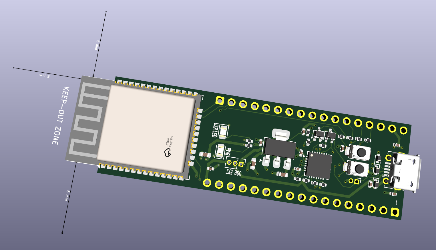
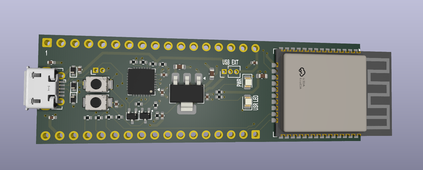
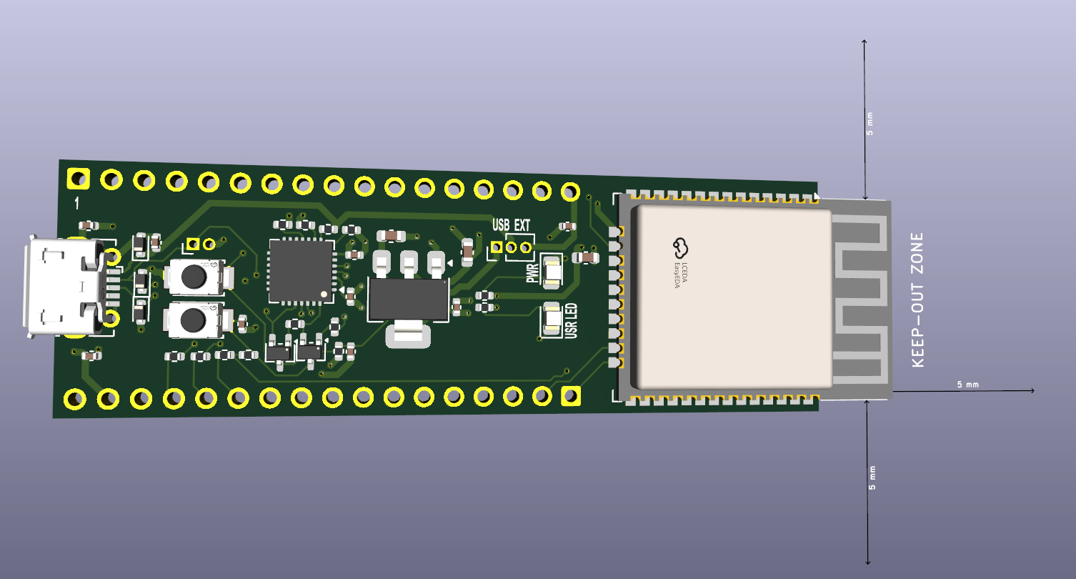
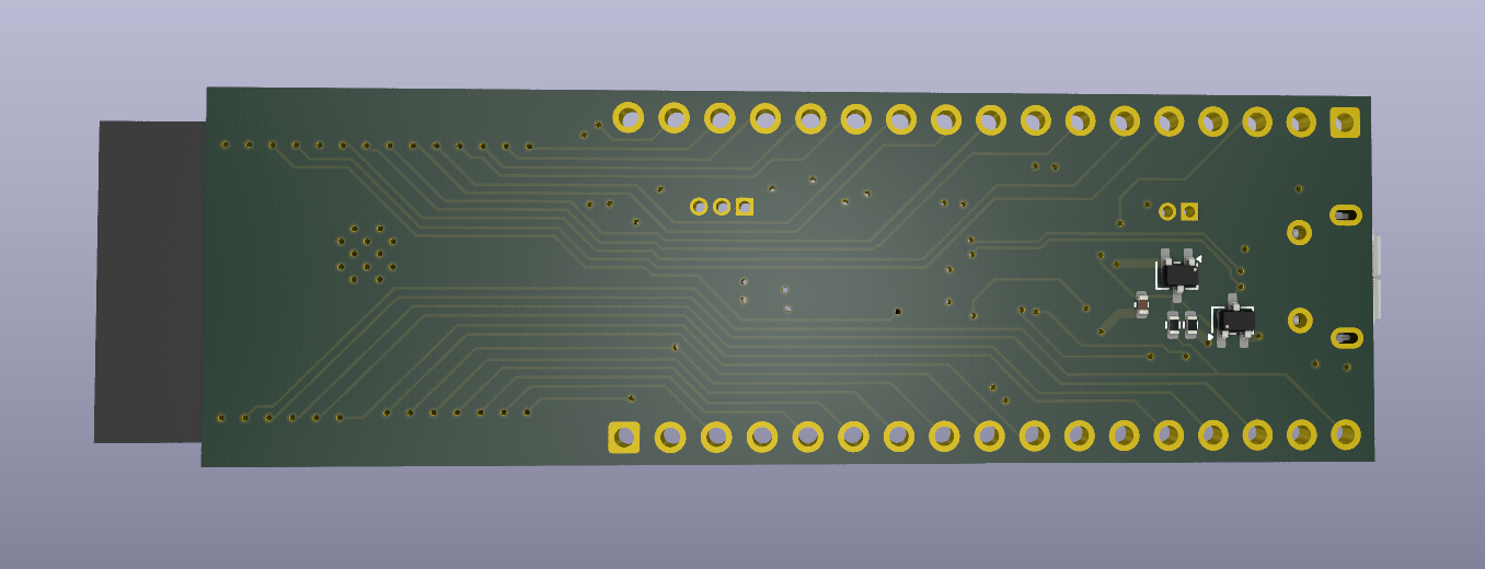
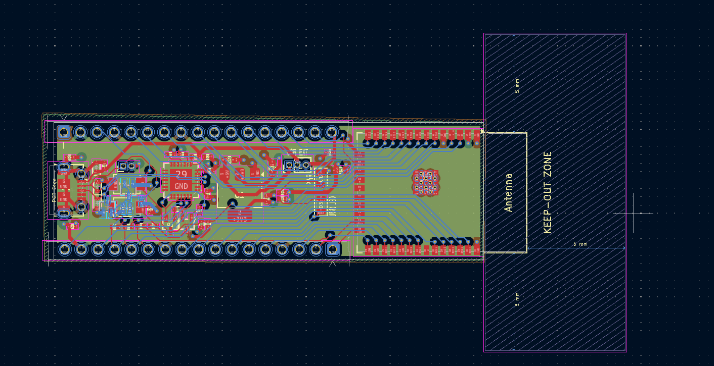
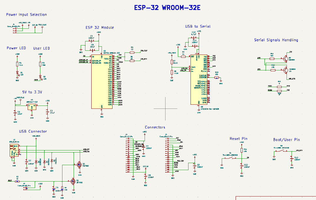
| Block | Key Components | Notes |
|---|---|---|
| ESP32 Module | ESP32-WROOM-32E | 38 pins exposed via castellated pads |
| USB-to-Serial | CP2102N, 2N7002 × 2 | Auto-reset circuit for one-click flashing |
| Power Regulation | AMS1117-3.3, SS8050 | 5V USB or external → 3.3V rail |
| ESD Protection | ESD5Zxx × 2 | On USB data lines |
| Decoupling | 100nF × 8, 22µF × 2, 10µF, 4.7µF | Distributed across power pins |
| Layer | Function |
|---|---|
| F.Cu | Signal routing + component pads |
| In1.Cu | Continuous ground plane |
| In2.Cu | Power distribution (3.3V, 5V) |
| B.Cu | Signal routing + component pads |
A dedicated ground plane on layer 2 ensures low-impedance return paths for high-speed USB signals and minimises EMI. Separating power onto its own inner layer reduces noise coupling to signal traces.
esptool.py to automatically put the ESP32 into bootloader mode — no manual button pressing needed during upload.Custom_ESP_Dev_Board/
├── hardware/ # KiCad project files (.kicad_pro, .kicad_sch, .kicad_pcb)
├── production/
│ ├── gerbers/ # Fabrication files
│ ├── BOM.csv # Bill of Materials
│ └── pick-and-place.csv # Assembly positions
├── docs/
│ ├── images/ # 3D renders, PCB layout, schematic screenshots
│ └── schematic.pdf # Exported schematic PDF
├── LICENSE
└── README.md.kicad_pro file in KiCad 9.0.7+This project is open-source hardware. See LICENSE for details.
Designed by Ghous Ali — Electronics & Embedded Systems Engineer
LinkedIn · Email
| Qty | Value | Footprint | References |
|---|---|---|---|
| 9 | 100nF | Capacitor_SMD:C_0402_1005Metric | C2, C4, C5, C7, C8, C9, C11, C12, C13 |
| 5 | 10k | Resistor_SMD:R_0402_1005Metric | R4, R10, R11, R12, R13 |
| 3 | ESD5Zxx | Diode_SMD:D_SOD-523 | D2, D4, D5 |
| 2 | 0 | Resistor_SMD:R_0402_1005Metric | R14, R15 |
| 2 | 1k | Resistor_SMD:R_0402_1005Metric | R2, R9 |
| 2 | 22 | Resistor_SMD:R_0402_1005Metric | R5, R6 |
| 2 | 22uF | Capacitor_SMD:C_0603_1608Metric | C3, C6 |
| 2 | 2N7002 | Package_TO_SOT_SMD:SOT-323_SC-70 | Q1, Q2 |
| 2 | Conn_01x17_Pin | Connector_Molex:Molex_SL_171971-0017_1x17_P2.54mm_Vertical | J4, J5 |
| 2 | LED | LED_SMD:LED_0805_2012Metric | D1, D3 |
| 2 | SS8050 | Package_TO_SOT_SMD:SOT-323_SC-70 | Q3, Q4 |
| 2 | TS-1088-AR02016 | TS-1088-AR02016 (1):SW_TS-1088-AR02016 | S1, S2 |
| 1 | 10uF | Capacitor_SMD:C_0603_1608Metric | C1 |
| 1 | 22.1k | Resistor_SMD:R_0402_1005Metric | R7 |
| 1 | 4.7uF | Capacitor_SMD:C_0402_1005Metric | C10 |
| 1 | 47.5k | Resistor_SMD:R_0402_1005Metric | R8 |
| 1 | 5.1k | Resistor_SMD:R_0402_1005Metric | R1 |
| 1 | 560 | Resistor_SMD:R_0402_1005Metric | R3 |
| 1 | AMS1117-3.3 | Package_TO_SOT_SMD:SOT-223-3_TabPin2 | U1 |
| 1 | CP2102N-Axx-xQFN28 | Package_DFN_QFN:QFN-28-1EP_5x5mm_P0.5mm_EP3.35x3.35mm | U3 |
| 1 | Conn_01x02_Pin | Connector_PinHeader_1.27mm:PinHeader_1x02_P1.27mm_Horizontal | J3 |
| 1 | Conn_01x03_Pin | Connector_PinHeader_1.27mm:PinHeader_1x03_P1.27mm_Vertical | J1 |
| 1 | ESP32-WROOM-32E | RF_Module:ESP32-WROOM-32D | U2 |
| 1 | USB_B_Micro | Connector_USB:USB_Micro-B_Molex-105017-0001 | J2 |
It measures 65.2 × 20.8 mm and has 4 copper layers, 1.6 mm thick.
47 parts, built around the ESP32-WROOM-32E, AMS1117-3.3, SS8050 and TS-1088-AR02016. The full list of its parts is on this page, with links to each part's symbol and footprint where PCBKit's library has them.
From the Ghous-Ali/Custom-ESP32-Dev-Board repository on GitHub, at the commit this page was made from: the board is hardware/TWLOG_v1.kicad_pcb and its schematic hardware/TWLOG_v1.kicad_sch. PCBKit opens the board in the browser, with nothing to install.
Its repository publishes it under the MIT licence: you may reuse it on that licence's terms (keep the author's notice, and for a copyleft licence share your changes alike).
SRA-VJTI/sra-board-hardware-design
ESP32-based Development Board for Robotics and Embedded Applications

emiirkaya/ThermovitalSync-PCB
A PCB project for a vital monitoring-cooling device with GUI

sukeshraom/ESP32-WROOM-32E-development-board
ESP32-WROOM-32E development board in the Arduino UNO form factor with USB Type-C and CH340C USB-to-UART interface. Includes complete KiCad schematic, PCB layout, and manufacturing files.

apoorvarshneya/ESP32_DevBoard
Designed and developed a custom ESP32 Development Kit from scratch using KiCad, featuring USB-to-Serial programming, 5V-to-3.3V power regulation, reset/boot buttons, LEDs, GPIO headers, and selectable power inputs.


lepetidozo/wledController_V1
I wanted to make a custom WLED controller for my bedroom's ledstrip and to learn more about electronics and PCB design
