
2 layers80 × 110 mm
NucDeck Left Controller PCB
dmcke5/NucDeck
The Open Source DIY Handheld Gaming PC!
59 parts561CERN-OHL-S-2.0
 ghostking2802/SmartHeater-CTRLModule
This project is a smart safety and control module for electric heaters. Designed using KiCad, it includes temperature monitoring, relay-based control, safety cutoffs, and visual feedback, all powered by a…
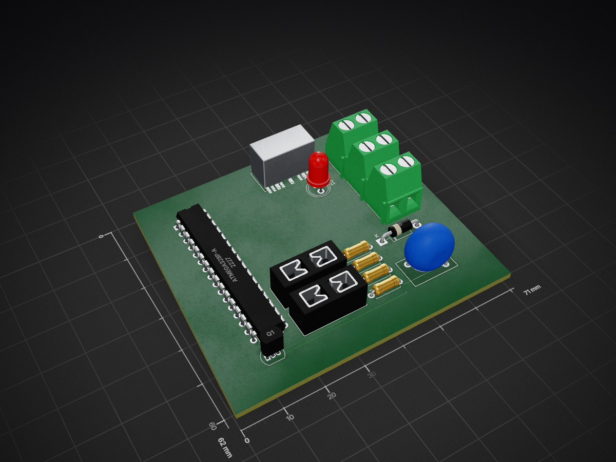
SmartHeaterControl is an open-source printed circuit board by ghostking2802, from the ghostking2802/SmartHeater-CTRLModule repository on GitHub. It is a 2-layer board of 71 × 62 mm with 15 parts on 34 nets, routed with 142 tracks and 7 vias.
It is built around the ATMEGA328P-AU. Its parts include 4 resistors, 2 diodes, 2 connectors, 2 fuses and 1 IC. It belongs with the AVR (ATmega, ATtiny) boards of this library.
This project is a smart safety and control module for electric heaters. Designed using KiCad, it includes temperature monitoring, relay-based control, safety cutoffs, and visual feedback, all powered by a microcontroller (e.g., ESP32 or Arduino).
| Component | Qty | Cost |
|---|---|---|
| ESP32 Dev Board | 1 | Rs. 300 |
| DS18B20 Temp Sensor | 1 | Rs. 100 |
| 5V Relay Module | 1 | Rs. 60 |
| OLED Display (0.96") | 1 | Rs. 150 |
| 7805 Regulator | 1 | Rs. 15 |
| Discrete Components | - | Rs. 50 |
| PCB Fabrication | 1 | Rs. 200 |
AC Mains → Step-down SMPS → 5V/12V Regulated Supply → Microcontroller → Relay Control
├── SmartHeaterControl.kicad_sch
├── SmartHeaterControl.kicad_pcb
├── gerber/
├── screenshots/
├── BlockDiagram.png
├── Schematic.png
└── PCB_View_*.png| Component | MCU Pin |
|---|---|
| DS18B20 Temp Sensor | GPIO 4 |
| Relay Module (IN) | GPIO 13 |
| OLED Display (I2C) | SDA = GPIO 21, SCL = GPIO 22 |
| Buzzer / LED | GPIO 14 |
| Manual Reset Button | GPIO 12 |
Note: DS18B20 needs a 4.7kΩ pull-up resistor on the data line.
OneWire.hDallasTemperature.hAdafruit_GFX.hAdafruit_SSD1306.hhttps://raw.githubusercontent.com/espressif/arduino-esp32/gh-pages/package_esp32_index.jsonSoumabha Majumdar
📧 soumabha.majumdar@gmail.com
📞 7003472159
This project is open-source and free to use for academic and non-commercial purposes.
#include <OneWire.h>
#include <DallasTemperature.h>
#include <Adafruit_GFX.h>
#include <Adafruit_SSD1306.h>

#define ONE_WIRE_BUS 4
#define RELAY_PIN 13
#define BUZZER_PIN 14
#define BUTTON_PIN 12

#define SCREEN_WIDTH 128
#define SCREEN_HEIGHT 64
Adafruit_SSD1306 display(SCREEN_WIDTH, SCREEN_HEIGHT, &Wire, -1);

OneWire oneWire(ONE_WIRE_BUS);
DallasTemperature sensors(&oneWire);

float cutoffTemp = 60.0;
float resumeTemp = 50.0;
bool manualReset = false;

void setup() {
  Serial.begin(115200);
sensors.begin();| Qty | Value | Footprint | References |
|---|---|---|---|
| 3 | R | Resistor_THT:R_Axial_DIN0207_L6.3mm_D2.5mm_P7.62mm_Horizontal | R1, R2, R4 |
| 2 | Conn_01x02 | TerminalBlock:TerminalBlock_bornier-2_P5.08mm | J1, J2 |
| 2 | Fuse | Fuse:Fuseholder_Blade_Mini_Keystone_3568 | F1, F2 |
| 1 | ATmega328P-A | Package_DIP:DIP-32_W7.62mm | U1 |
| 1 | D | Diode_THT:D_DO-41_SOD81_P10.16mm_Horizontal | D1 |
| 1 | Heater | TerminalBlock:TerminalBlock_bornier-2_P5.08mm | R3 |
| 1 | LED | LED_THT:LED_D5.0mm | D2 |
| 1 | Q1 | Package_TO_SOT_THT:TO-92_Inline | Q1 |
| 1 | Relay_SPDT | Relay_SMD:Relay_SPDT_AXICOM_HF3Series_50ohms_Pitch1.27mm | K1 |
| 1 | Thermistor_NTC | Resistor_THT:R_Axial_DIN0207_L6.3mm_D2.5mm_P7.62mm_Horizontal | TH1 |
| 1 | Varistor | Varistor:RV_Disc_D12mm_W7.9mm_P7.5mm | RV1 |
It measures 71 × 62 mm and has 2 copper layers, 1.6 mm thick.
15 parts, built around the ATMEGA328P-AU. The full list of its parts is on this page, with links to each part's symbol and footprint where PCBKit's library has them.
From the ghostking2802/SmartHeater-CTRLModule repository on GitHub, at the commit this page was made from: the board is SmartHeaterControl.kicad_pcb and its schematic SmartHeaterControl.kicad_sch. PCBKit opens the board in the browser, with nothing to install.
Its repository states no licence, so its author keeps all rights: ask ghostking2802 before reusing the design.
dmcke5/NucDeck
The Open Source DIY Handheld Gaming PC!


profdc9/RFBitBanger
A QRP digital transceiver created from readily available parts for off-the-grid maintenance

futureshocked/KLP4e_MCU-Datalogger
This is the repository for the "MCU Datalogger" project.


sportiduino/sportiduino
Electronic timing system for orienteering and similar outdoor sports events on Arduino

SukkoPera/OpenPSX2AmigaPadAdapter
Playstation to Commodore Amiga/CD32 Controller Adapter

4x1md/vx8_gps
DIY GPS module for Yaesu VX-8DR/VX-8DE handheld transceiver.